Amateur Radio Homebrew (Shack Culture)
-
Stanley

- Global Moderator

- Posts: 90321
- Joined: 23 Jan 2012, 12:01
- Location: Barnoldswick. Nearer to Heaven than Gloria.
Re: Amateur Radio Homebrew (Shack Culture)
Tidy.....
Stanley Challenger Graham
Stanley's View
scg1936 at talktalk.net
"Beware of certitude" (Jimmy Reid)
The floggings will continue until morale improves!
Stanley's View
scg1936 at talktalk.net
"Beware of certitude" (Jimmy Reid)
The floggings will continue until morale improves!
-
PanBiker

- Site Administrator

- Posts: 16450
- Joined: 23 Jan 2012, 13:07
- Location: Barnoldswick - In the West Riding of Yorkshire, always was, always will be.
Re: Amateur Radio Homebrew (Shack Culture)
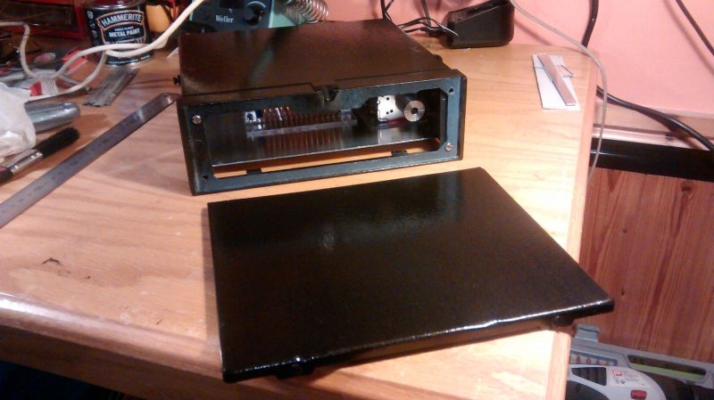
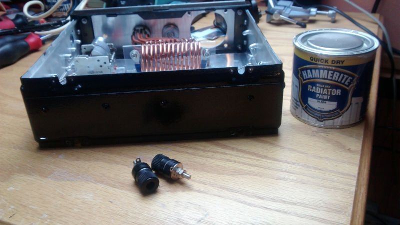
The recycled Pye Westmister case has now been painted, two coats of black Hammerite and it's come up quite well.
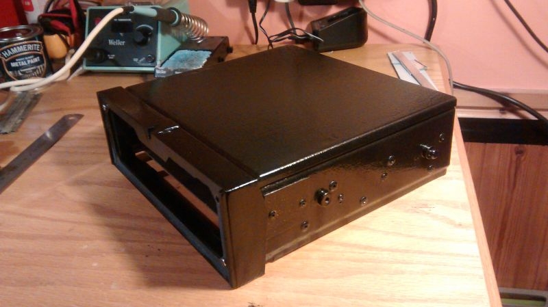
The side and back blanking plates have covered well
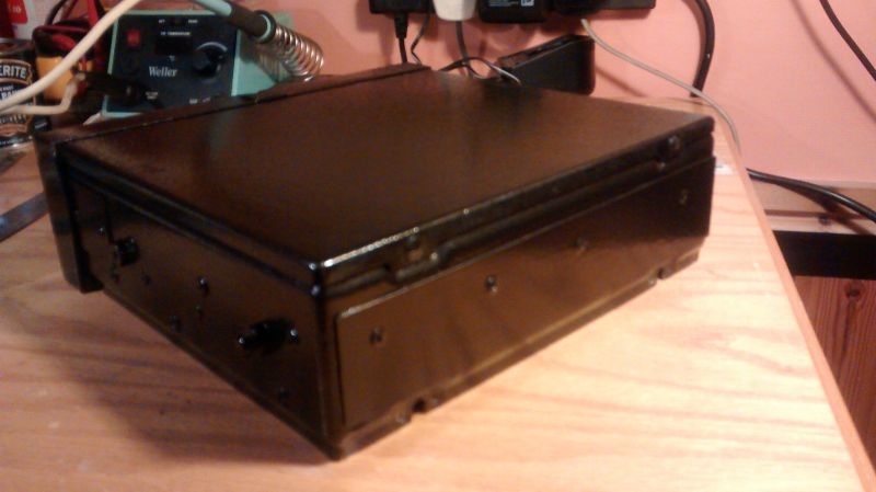
When the front panel and it's coloured fascia and annotations are finalised and in place it should look OK
I can move on now to the internal wiring. At the same time I'm looking at various options for making the paper mask for the annotations. It will have to be accurate in order to line up with the front panel controls and flanged knobs. Open Office Draw being explored at the moment.
The side and back blanking plates have covered well
When the front panel and it's coloured fascia and annotations are finalised and in place it should look OK
I can move on now to the internal wiring. At the same time I'm looking at various options for making the paper mask for the annotations. It will have to be accurate in order to line up with the front panel controls and flanged knobs. Open Office Draw being explored at the moment.
Ian
-
Stanley
- Global Moderator
- Posts: 90321
- Joined: 23 Jan 2012, 12:01
- Location: Barnoldswick. Nearer to Heaven than Gloria.
Re: Amateur Radio Homebrew (Shack Culture)
Now Hammerite I do understand!
Stanley Challenger Graham
Stanley's View
scg1936 at talktalk.net
"Beware of certitude" (Jimmy Reid)
The floggings will continue until morale improves!
Stanley's View
scg1936 at talktalk.net
"Beware of certitude" (Jimmy Reid)
The floggings will continue until morale improves!
-
PanBiker
- Site Administrator
- Posts: 16450
- Joined: 23 Jan 2012, 13:07
- Location: Barnoldswick - In the West Riding of Yorkshire, always was, always will be.
Re: Amateur Radio Homebrew (Shack Culture)
We have both granddaughters with us this week so I didn't think I would get much time to further the project. As it has turned out I have managed a few hours in the afternoons when the girls have been out with Sally.
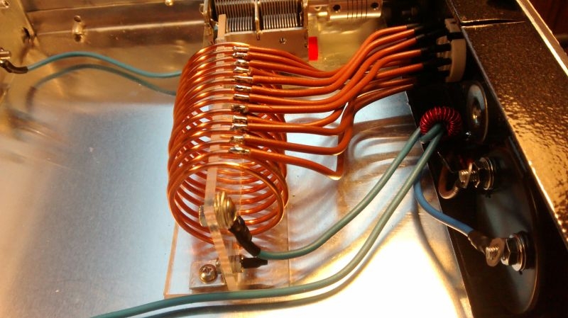
I have moved on to the internal wiring now. First job was to put the coil tappings on and wire these up to the 12 way switch. I have 14 turns on the coil and need 12 taps so I have used the middle coils and skipped one at each end. The wiring is 1.5mm single core insulated cable stripped from twin and earth lighting cable. I'm using the brown for the coil tappings and switch and will use blue for the rest of the interconnections.
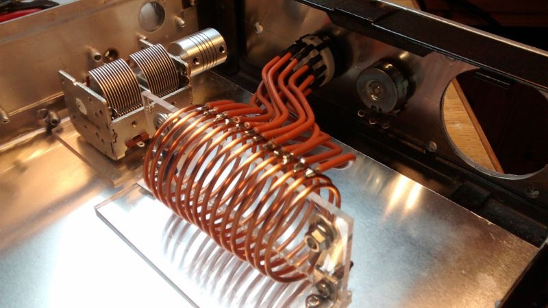
The observant will notice, (as I did whilst doing the point to point wiring) that the insulated perspex mounting for the coil is actually fitted the wrong way round. I have altered this now and it now aligns with the insulation under the capacitor as was the original intention.
Here is a close up of the switch connections, I have fitted heat shrink over the connections for neatness. The 1.5mm solid core cable is quite rigid and will not require any cable ties or further support.
I had to start at 6 o'clock with the wiring to the switch and work both clockwise and anticlockwise from the bottom to ensure I could get the 100w Weller instant heat gun in to solder the connections.
The original Pye Westminster transceiver had it's front panel secured with four 4BA slotted pan head machine screws, not very nice to look at. As I have fitted an extra layer with the perspex front these were not only ugly but no longer long enough They screwed into tapped bushes on the front of the case. I have decided to fit nicer screws but I did not have any quite long enough in my existing stock of stainless steel metric screws. I ordered a small range of various head types to expand my collection. I have added 4mm Round, Domed and Flanged Allen Head. I drilled out the threads on the old 4BA bushes to take the new screws and will secure them with Nylec nuts in the final fixing. Not made my mind up yet which style to use but am favouring the flanged headed ones as these match well with the flanged knobs I will be using for the main front panel controls.
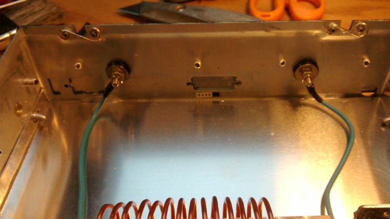
Something else I realised was that I did not have a matching pair of terminal posts for the two connections required on the back panel. I called into Emery Electronics in Nelson the other day and picked up a couple. Unfortunately Nick didn't have matching types in different colours. I could have had two red in one style or two black in a different style so I opted for the black. In use one of these terminals will connect to the earth connection on my transceiver and the other will connect to a random length of wire which will be tuned by the unit into the artificial earth. They are heavy duty to handle the large currents that may be present in the circuit in operation. They will need some form of ID on the terminals to avoid incorrect connection.
As the case is now painted up black I have decided to change a portion of the back panel to white. I have some Hammerite white radiator gloss that will do the job. The terminals need a 10mm mounting hole for the through chassis insulating bush. Once these are drilled I will mask a rectangle off on the back and over paint with the white. To indicate which connection is which I may mount a small perspex disc on each terminal post and annotate or colour code the connections.
I have moved on to the internal wiring now. First job was to put the coil tappings on and wire these up to the 12 way switch. I have 14 turns on the coil and need 12 taps so I have used the middle coils and skipped one at each end. The wiring is 1.5mm single core insulated cable stripped from twin and earth lighting cable. I'm using the brown for the coil tappings and switch and will use blue for the rest of the interconnections.
The observant will notice, (as I did whilst doing the point to point wiring) that the insulated perspex mounting for the coil is actually fitted the wrong way round. I have altered this now and it now aligns with the insulation under the capacitor as was the original intention.
Here is a close up of the switch connections, I have fitted heat shrink over the connections for neatness. The 1.5mm solid core cable is quite rigid and will not require any cable ties or further support.
I had to start at 6 o'clock with the wiring to the switch and work both clockwise and anticlockwise from the bottom to ensure I could get the 100w Weller instant heat gun in to solder the connections.
The original Pye Westminster transceiver had it's front panel secured with four 4BA slotted pan head machine screws, not very nice to look at. As I have fitted an extra layer with the perspex front these were not only ugly but no longer long enough They screwed into tapped bushes on the front of the case. I have decided to fit nicer screws but I did not have any quite long enough in my existing stock of stainless steel metric screws. I ordered a small range of various head types to expand my collection. I have added 4mm Round, Domed and Flanged Allen Head. I drilled out the threads on the old 4BA bushes to take the new screws and will secure them with Nylec nuts in the final fixing. Not made my mind up yet which style to use but am favouring the flanged headed ones as these match well with the flanged knobs I will be using for the main front panel controls.
Something else I realised was that I did not have a matching pair of terminal posts for the two connections required on the back panel. I called into Emery Electronics in Nelson the other day and picked up a couple. Unfortunately Nick didn't have matching types in different colours. I could have had two red in one style or two black in a different style so I opted for the black. In use one of these terminals will connect to the earth connection on my transceiver and the other will connect to a random length of wire which will be tuned by the unit into the artificial earth. They are heavy duty to handle the large currents that may be present in the circuit in operation. They will need some form of ID on the terminals to avoid incorrect connection.
As the case is now painted up black I have decided to change a portion of the back panel to white. I have some Hammerite white radiator gloss that will do the job. The terminals need a 10mm mounting hole for the through chassis insulating bush. Once these are drilled I will mask a rectangle off on the back and over paint with the white. To indicate which connection is which I may mount a small perspex disc on each terminal post and annotate or colour code the connections.
Ian
-
Stanley
- Global Moderator
- Posts: 90321
- Joined: 23 Jan 2012, 12:01
- Location: Barnoldswick. Nearer to Heaven than Gloria.
Re: Amateur Radio Homebrew (Shack Culture)
It's a work of art......
Stanley Challenger Graham
Stanley's View
scg1936 at talktalk.net
"Beware of certitude" (Jimmy Reid)
The floggings will continue until morale improves!
Stanley's View
scg1936 at talktalk.net
"Beware of certitude" (Jimmy Reid)
The floggings will continue until morale improves!
-
PanBiker
- Site Administrator
- Posts: 16450
- Joined: 23 Jan 2012, 13:07
- Location: Barnoldswick - In the West Riding of Yorkshire, always was, always will be.
Re: Amateur Radio Homebrew (Shack Culture)
Best laid plans and all that.. I tried over painting the black crackle finish Hammerite with the white Hammerite gloss but found that it is water based and would not cover the black well. After two coates it was still not a good finish so I removed it along with some of the previously painted black! Upshot is, I have had to repaint the back panel in the crackle finish. Only thing that went right on that session was drilling the 10mm holes for the terminals, at least they are right.
I will stick to plan B and put a perspex disk with some form of suitable annotation behind to identify the terminals.
I will stick to plan B and put a perspex disk with some form of suitable annotation behind to identify the terminals.
Ian
-
PanBiker
- Site Administrator
- Posts: 16450
- Joined: 23 Jan 2012, 13:07
- Location: Barnoldswick - In the West Riding of Yorkshire, always was, always will be.
Re: Amateur Radio Homebrew (Shack Culture)
I had convinced myself that I already had stock of the diode I needed for the meter drive circuitry, I was wrong, I have everything but! I called in at Nicks again in Nelson for the 1N34A germanium diode required. This is an old type and is now no longer manufactured, neither is it's direct equivalent so I have opted for a slightly higher spec device its still a germanium junction type so will do the job just the same with a bit of overkill, nowt wrong with that.
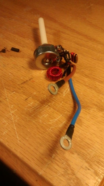
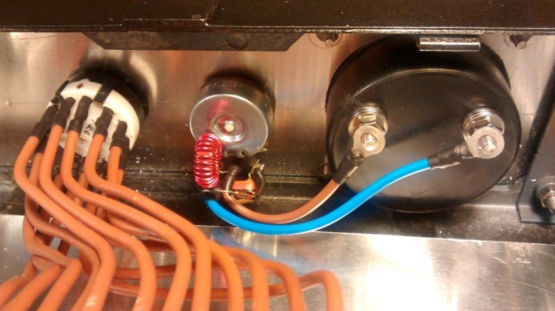
With all the bits now in hand, I have constructed the meter driving circuitry on the back of its adjusting potentiometer. The circuit consists of the small toroid transformer that I wound earlier. This is used to bleed off a small amount of current from the tuned circuit to drive the meter movement. The diode is used to rectify the current to produce a DC drive for the meter, a small 10nf capacitor across the coil is used to smooth the current and the variable resistor in the circuit to adjust the level of drive applied to the meter movement. I have created two pigtails with crimped ring connectors for the meter.
Having all the components built on the back of the pot with only the necessary connections feeding the meter allows me to detach the meter easily as this is the only component mounted from the front. It needs to be easily detachable as I still have to split down the front escutcheon arrangement to insert the annotation sheet for the front decals. All the rest of the components are back or chassis mounted and will only need their retaining nuts removing to allow removal of the front perspex panel. Here is the pot with all the components mounted.
Here it is mounted back in the case. No point doing the final connections to the meter yet but I'm happy with the length of the leads for the meter. I have orientated the toroid vertically on the back of the pot. The primary drive current will be provided by feeding a length of small diameter coaxial cable through the centre of the toroid. This cable will be the output line from the tuned circuit made by the coil and variable capacitor, (L C Network) and after passing through the toroid will be connected to the output terminal on the back.
It's starting to look like a circuit now.
Ian
-
Stanley
- Global Moderator
- Posts: 90321
- Joined: 23 Jan 2012, 12:01
- Location: Barnoldswick. Nearer to Heaven than Gloria.
Re: Amateur Radio Homebrew (Shack Culture)
I don't understand it but it is quite beautiful! If a thing looks right, it usually is.....
Stanley Challenger Graham
Stanley's View
scg1936 at talktalk.net
"Beware of certitude" (Jimmy Reid)
The floggings will continue until morale improves!
Stanley's View
scg1936 at talktalk.net
"Beware of certitude" (Jimmy Reid)
The floggings will continue until morale improves!
-
PanBiker
- Site Administrator
- Posts: 16450
- Joined: 23 Jan 2012, 13:07
- Location: Barnoldswick - In the West Riding of Yorkshire, always was, always will be.
Re: Amateur Radio Homebrew (Shack Culture)
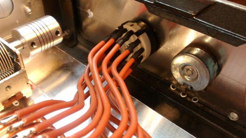
Continuing with the wiring, the next job was to decide how to create a primary winding for the toroid transformer. The design I'm following used a length of coaxial cable using only the inner conductor passed through the centre of the toroid. The UR67 coax I have is just a little oversized so I have decided to use couple of turns of the 1.5mm cable used for the rest of the wiring. Here it is passed a couple of times through the toroid.
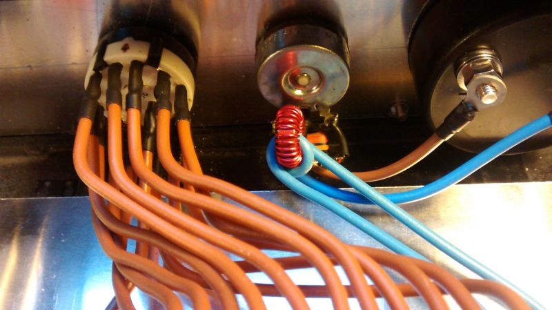
This cable is fed from one end of the LC tuned circuit, here it is connected to one end of the tapped coil. I have used crimped ring connectors wherever possible for easy connection to the various termination points.
After passing from the coil through the toroid, the connection then goes to one of the rear terminal posts shown on the left. This in turn will be connected to the chassis (earth) connection on the transceiver.
The other side of the LC tuned circuit from one side of the variable capacitor is fed to the other rear terminal post. A random length of wire will be connected to this terminal and will be tuned for maximum current flow in the wire when transmitting and will act as the artificial earth or counterpoise for the antenna system.
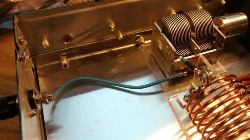
You can see that the other end of the coil is connected to the variable capacitor, this series connection forms the simple LC tuning network within the design.
All the internal wiring is now complete and all that is left to do now is to cut down the spindles on the controls to a suitable length for the front panel knobs and then annotate the controls and connectors. In practice I will hook it up for an initial test to see if my arrangement for the primary drive for the toroid on the meter drive circuit works OK.
This cable is fed from one end of the LC tuned circuit, here it is connected to one end of the tapped coil. I have used crimped ring connectors wherever possible for easy connection to the various termination points.
After passing from the coil through the toroid, the connection then goes to one of the rear terminal posts shown on the left. This in turn will be connected to the chassis (earth) connection on the transceiver.
The other side of the LC tuned circuit from one side of the variable capacitor is fed to the other rear terminal post. A random length of wire will be connected to this terminal and will be tuned for maximum current flow in the wire when transmitting and will act as the artificial earth or counterpoise for the antenna system.
You can see that the other end of the coil is connected to the variable capacitor, this series connection forms the simple LC tuning network within the design.
All the internal wiring is now complete and all that is left to do now is to cut down the spindles on the controls to a suitable length for the front panel knobs and then annotate the controls and connectors. In practice I will hook it up for an initial test to see if my arrangement for the primary drive for the toroid on the meter drive circuit works OK.
Ian
-
Stanley
- Global Moderator
- Posts: 90321
- Joined: 23 Jan 2012, 12:01
- Location: Barnoldswick. Nearer to Heaven than Gloria.
Re: Amateur Radio Homebrew (Shack Culture)
I don't understand a word of it but it looks right! Tidy work Ian.....
Stanley Challenger Graham
Stanley's View
scg1936 at talktalk.net
"Beware of certitude" (Jimmy Reid)
The floggings will continue until morale improves!
Stanley's View
scg1936 at talktalk.net
"Beware of certitude" (Jimmy Reid)
The floggings will continue until morale improves!
-
PanBiker
- Site Administrator
- Posts: 16450
- Joined: 23 Jan 2012, 13:07
- Location: Barnoldswick - In the West Riding of Yorkshire, always was, always will be.
Re: Amateur Radio Homebrew (Shack Culture)
Thanks Stanley, I'll see what happens when I introduce it to my station..
Ian
-
Stanley
- Global Moderator
- Posts: 90321
- Joined: 23 Jan 2012, 12:01
- Location: Barnoldswick. Nearer to Heaven than Gloria.
Re: Amateur Radio Homebrew (Shack Culture)
I'll lay a small bet it will be a great improvement.....
Stanley Challenger Graham
Stanley's View
scg1936 at talktalk.net
"Beware of certitude" (Jimmy Reid)
The floggings will continue until morale improves!
Stanley's View
scg1936 at talktalk.net
"Beware of certitude" (Jimmy Reid)
The floggings will continue until morale improves!
-
PanBiker
- Site Administrator
- Posts: 16450
- Joined: 23 Jan 2012, 13:07
- Location: Barnoldswick - In the West Riding of Yorkshire, always was, always will be.
Re: Amateur Radio Homebrew (Shack Culture)
I have made new earthing strap leads with ring connectors on each end. The transceiver, antenna matching unit and the new ground tuners earth connections are all connected together. The other connection to the tuner is a random length of wire which I already have round the skirting board in the loft. Driving the antenna with a carrier should produce a complimentary signal flow in the earthing circuit, the tuned circuit within the unit is used to peak the current flowing in the artificial ground wire.
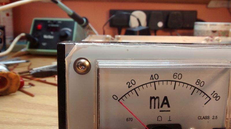
I hooked it up and did a few tests on various bands. At the moment I cant get any forward current indication on the meter. I think the problem may be the level of drive being picked up by the meter sensing transformer. My couple of turns through the toroid may well not be enough. I will have to rethink this section and try a different approach. I suppose this is a little bit like fitting in engineering terms
I hooked it up and did a few tests on various bands. At the moment I cant get any forward current indication on the meter. I think the problem may be the level of drive being picked up by the meter sensing transformer. My couple of turns through the toroid may well not be enough. I will have to rethink this section and try a different approach. I suppose this is a little bit like fitting in engineering terms
Ian
-
Stanley
- Global Moderator
- Posts: 90321
- Joined: 23 Jan 2012, 12:01
- Location: Barnoldswick. Nearer to Heaven than Gloria.
Re: Amateur Radio Homebrew (Shack Culture)
Exactly the same Ian. You make it and then fine tune the fit and actual performance. The bearings for the shaft I am making at the moment are a good example. The shaft turns like silk at the moment but when bolted down tight there may have to be adjustments to the fit. They call it engineering!
Stanley Challenger Graham
Stanley's View
scg1936 at talktalk.net
"Beware of certitude" (Jimmy Reid)
The floggings will continue until morale improves!
Stanley's View
scg1936 at talktalk.net
"Beware of certitude" (Jimmy Reid)
The floggings will continue until morale improves!
-
PanBiker
- Site Administrator
- Posts: 16450
- Joined: 23 Jan 2012, 13:07
- Location: Barnoldswick - In the West Riding of Yorkshire, always was, always will be.
Re: Amateur Radio Homebrew (Shack Culture)
My HF wire antenna is currently disconnected and the ladder cable that makes up the main run is temporarily taped back the mast for my tri-band vertical antenna. It had to come down as it was a trip hazard for the roofers that have been working for me. I took the opportunity to get the toroidal driving transformer and feed cable back inside to give them a bit of TLC. The brass terminals that connect into the ladder cable have been open to the elements and have a bit of minor corrosion. I have cleaned these up, I popped off the lid to have a look at the toroid and its windings, took a bit of doing as I had run a bead of glue round when I put it on to stop water ingress. All was OK inside the box so I closed it back up again.
To stop further weathering on the brass connector terminals when I redeploy I have decided to double box the entire unit. I had a quick nip round the shops to find something suitable and settled on a sandwich box, one of those with a neoprene seal and the four hinged closing flaps on the sides, Just the job and a good fit for the box still allowing a bit of room for connecting the ladder line in. I have cut a slotted hole on what will be the bottom of the box when it is put back in place. I have attached a plastic hanging hook to the top to secure it back to the steel eye fixing point on the chimney, the ladder line is secured here also using a carabina and a short length of paracord to provide isolation. A hole in the side for a grommet for the feed cable. I glued the control box to the bottom of the sandwich box so it's nice and stable. I have sealed the cable entry and the mounting holes for the hanging hook with silicone and will run a bead round the lid when I have remade the ladder line connections and pop the lid on. I think I will give the terminals a coat as well when I have remade the connections. This should make it a lot more watertight.
Just waiting for a suitable time to redeploy. Roofers have finished on mine but the scaffold is still up so an ideal opportunity for reinstallation. I might get to it this afternoon if the day holds up. I have a taxi job late morning so I'll see what its like when I get back.
Ian
-
Stanley
- Global Moderator
- Posts: 90321
- Joined: 23 Jan 2012, 12:01
- Location: Barnoldswick. Nearer to Heaven than Gloria.
Re: Amateur Radio Homebrew (Shack Culture)
Those boxes with the four flaps are good. I use them in the shed for storing small tools and accessories. You'll have got it back up as it was dry but that was a cold wind!
Stanley Challenger Graham
Stanley's View
scg1936 at talktalk.net
"Beware of certitude" (Jimmy Reid)
The floggings will continue until morale improves!
Stanley's View
scg1936 at talktalk.net
"Beware of certitude" (Jimmy Reid)
The floggings will continue until morale improves!
-
PanBiker
- Site Administrator
- Posts: 16450
- Joined: 23 Jan 2012, 13:07
- Location: Barnoldswick - In the West Riding of Yorkshire, always was, always will be.
Re: Amateur Radio Homebrew (Shack Culture)
No roof for me yesterday Stanley, discretion better than valour. I got up on the scaffold to tidy and remake the ends of the ladder cable but the wind was not only bitter there were some very heavy gusts up at roof level. It's still ready and waiting for a better day, there's no rush as long as I can get to it before the scaffold goes. The lads haven't started pointing next door yet so I can bide my time for a flat day.
Ian
-
Stanley
- Global Moderator
- Posts: 90321
- Joined: 23 Jan 2012, 12:01
- Location: Barnoldswick. Nearer to Heaven than Gloria.
Re: Amateur Radio Homebrew (Shack Culture)
Sensible man. My steeplejack mate Peter Tatham always wore an ex-WD leather jerkin. He reckoned that when that started flapping it was time to get down.....
Stanley Challenger Graham
Stanley's View
scg1936 at talktalk.net
"Beware of certitude" (Jimmy Reid)
The floggings will continue until morale improves!
Stanley's View
scg1936 at talktalk.net
"Beware of certitude" (Jimmy Reid)
The floggings will continue until morale improves!
-
PanBiker
- Site Administrator
- Posts: 16450
- Joined: 23 Jan 2012, 13:07
- Location: Barnoldswick - In the West Riding of Yorkshire, always was, always will be.
Re: Amateur Radio Homebrew (Shack Culture)
Nathan delivered me an extending cat ladder yesterday. I couldn't get to it today as Uniblast were sandblasting next doors wall prior to it being re pointed. I am hoping to get the antenna sorted before the guys turn up for next door. I'm on a countdown now as Matt called to say the scaffold will be going after they have finished there. Glad of the cat ladder, my roof has a proper coating of sand all over it, sandblasting does a good job but it does produce a lot of dust. I could do with it chucking it down overnight but I don't think it will.
Ian
-
Stanley
- Global Moderator
- Posts: 90321
- Joined: 23 Jan 2012, 12:01
- Location: Barnoldswick. Nearer to Heaven than Gloria.
Re: Amateur Radio Homebrew (Shack Culture)
And it ends up in the gutters......
Stanley Challenger Graham
Stanley's View
scg1936 at talktalk.net
"Beware of certitude" (Jimmy Reid)
The floggings will continue until morale improves!
Stanley's View
scg1936 at talktalk.net
"Beware of certitude" (Jimmy Reid)
The floggings will continue until morale improves!
-
PanBiker
- Site Administrator
- Posts: 16450
- Joined: 23 Jan 2012, 13:07
- Location: Barnoldswick - In the West Riding of Yorkshire, always was, always will be.
Re: Amateur Radio Homebrew (Shack Culture)
Spent the morning re-deploying my HF wire antenna. One of Matt's lads tipped up this morning and set to pointing next doors wall so I thought I had better get a shift on. Once I had the cat ladder on the top of the scaffold I had to extend it nearly to it's limit. I reconnected the main ribbon feeder which is the radiating section of the antenna first. It's 20M long and is fastened at it's far end onto the far corner of the gable on Bessie Street, the other end which is connected to the feeder via it's toroid transformer design is secured back to the chimney stack. Both ends are isolated using paracord and secured by carabina's to heavy duty stainless steel screw eyes drilled and plugged into the masonry at each end, both are directly into the body of the stone rather than secured in the joints. I installed an insulated hook on the transformer box which is also fastened to the eye on the stack, the feeder cable from the box to the transceiver has half a dozen turns wound into a 9" coil to form a common mode choke. This is held together with cable ties and hung and fastened to the mounting point. This stops stray RF from travelling back down the feeder, high power RF can bite with a nasty burn if allowed to be fed back to the equipment.
The feeder cable was already connected to the box so that I could weatherproof the entry. After attaching the radiating section to the fixing point this left the cables on the wrong side of the cat ladder as I had to run the ladder up between the stack and the velux where the cable enters the loft. Fortunately it was long enough to take it up to the top and over the ridge and with a bit of coaxing I managed to wrangle it round and under the end of the claw end of the ladder. Its tied down to the slates with lengths of wire bent into a "U" shapes and pushed up under the bottom edges of the slates. With the radiating line in position it runs about 4" above the ladder so fouls with the cat when you flip it over onto its wheels to take it down, the claw and is uppermost then and it grabs the cable on the way down. I had to do a bit of careful manipulation of the ladder with it on it's side to ease it down past the installation. I was glad of scaffolding for this manoeuvre, I remember it well from when we originally deployed it from the top of a ladder.
Anyway, all sorted now so after a bit of lunch I fired the station up and tested it across all the bands it covers. I had a brief contact with a 9A7 station in Croatia who was working a contest, he gave me a 59 signal report which is as good as it gets, 5 is fully readable and the 9 is for signal strength. My automatic ATU likes it as well and can resonate the antenna on all bands.
Ian
-
Stanley
- Global Moderator
- Posts: 90321
- Joined: 23 Jan 2012, 12:01
- Location: Barnoldswick. Nearer to Heaven than Gloria.
Re: Amateur Radio Homebrew (Shack Culture)
All Greek to me but up to your usual standards!
Stanley Challenger Graham
Stanley's View
scg1936 at talktalk.net
"Beware of certitude" (Jimmy Reid)
The floggings will continue until morale improves!
Stanley's View
scg1936 at talktalk.net
"Beware of certitude" (Jimmy Reid)
The floggings will continue until morale improves!
-
PanBiker
- Site Administrator
- Posts: 16450
- Joined: 23 Jan 2012, 13:07
- Location: Barnoldswick - In the West Riding of Yorkshire, always was, always will be.
Re: Amateur Radio Homebrew (Shack Culture)
New anti-static mat for the repair on my transceiver as noted in the other thread did not turn up today. Stayed in for it but to no avail. I would rather be safe than sorry as the board has to be completely removed from the chassis to effect the repair, so no progress on this today. I took the top cover off the other day to identify the fault and took a few pictures to illustrate the problem. I will put them up in due course.
Ian
-
PanBiker
- Site Administrator
- Posts: 16450
- Joined: 23 Jan 2012, 13:07
- Location: Barnoldswick - In the West Riding of Yorkshire, always was, always will be.
Re: Amateur Radio Homebrew (Shack Culture)
The anti-static mat turned up the day after my last post so I have started the repair steady away. As you will see later I have run into a slight problem.
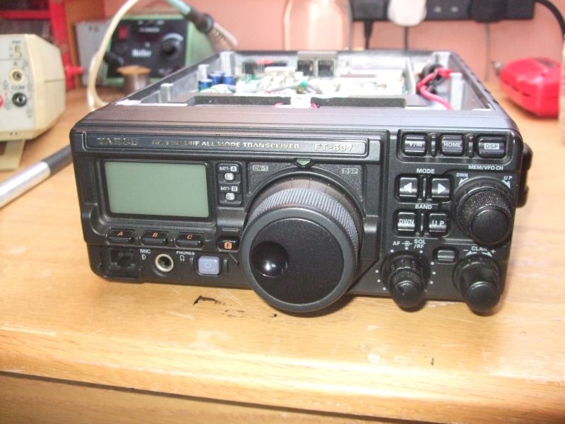
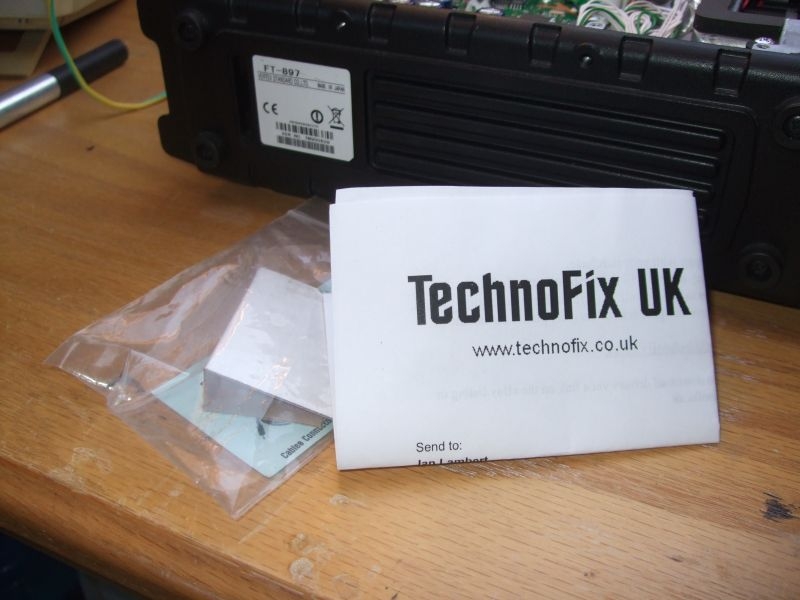
First of all here is the transceiver on the bench, just to refresh the memory this is a multimode HF/VHF transceiver with general coverage receiver.
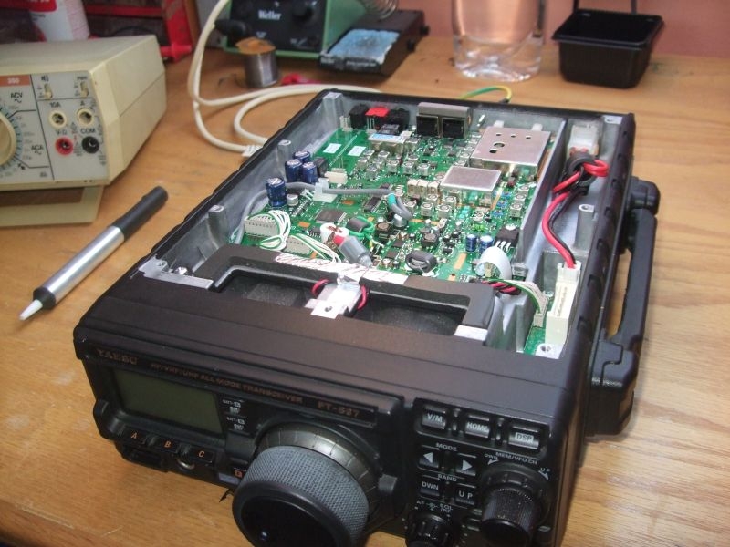
Here again with the lid off showing a better view of the top panel which is the one we are interested in.
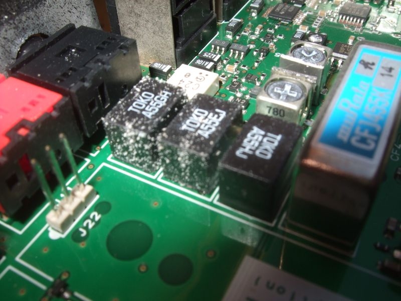
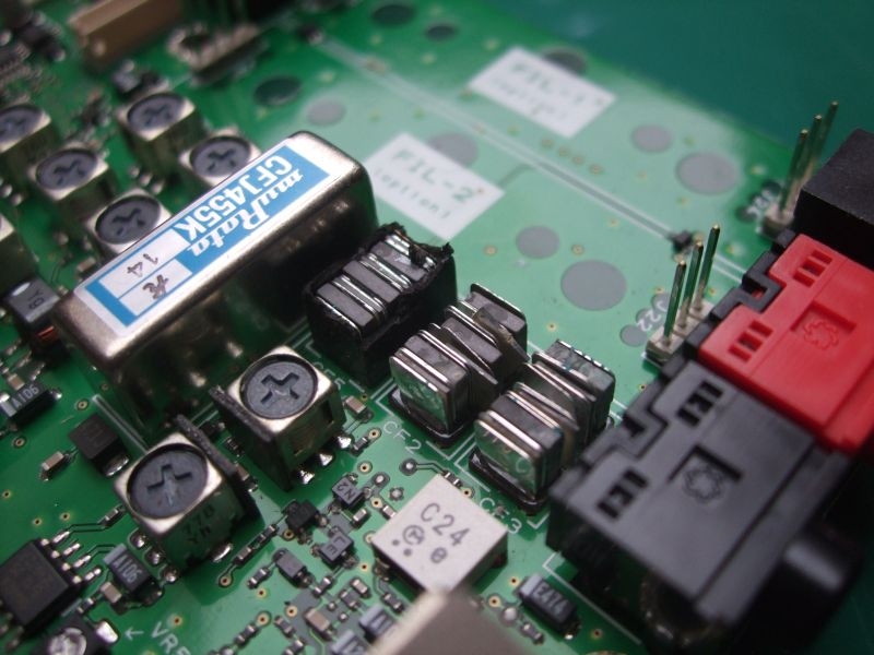
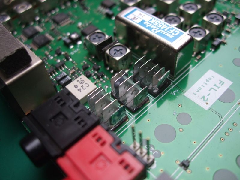
Here are the Ceramic IF Filters which are the cause of the insensitivity on the VHF bands, three filters in all for 6KHz, 9KHz and 12KHz. You can see the salts caused by moisture within the plastic encapsulation leeching to the surface. Two look to be severely damaged, the third looks reasonably OK. The moisture essentially destroys the insulation and corrodes the plates within the filters rendering them useless, severely attenuating the IF (Intermediate Frequency) stages of the receiver, these particular filters are only relevant to the VHF section of the receiver.
Here are the replacements that I got from Technofix via their Ebay shop, just realised I didn't take them out of the bag, I'll put a better picture up when I fit them.
I did not want to start proper disassembly until I had the anti-static matting and a proper earth environment to work from. Here is the mat it's 400 x 300mm and is a nice fit from front to back on the bench.
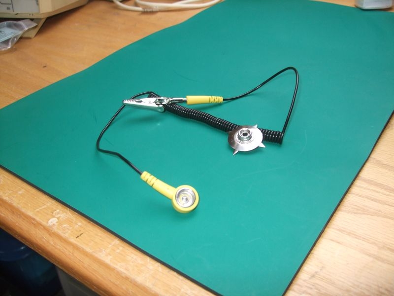
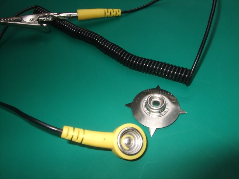
The mat is conductive rubber of some type, it's black on the back. The press stud connector is supplied loose so that you can fit it wherever you want on the mat, I connected mine in the back corner. The prongs are bent down and pushed through the mat from the top then opened up on the bottom effectively gripping both surfaces of the mat. Press stud, curly cable and crocodile clip to connect to your earthing point.
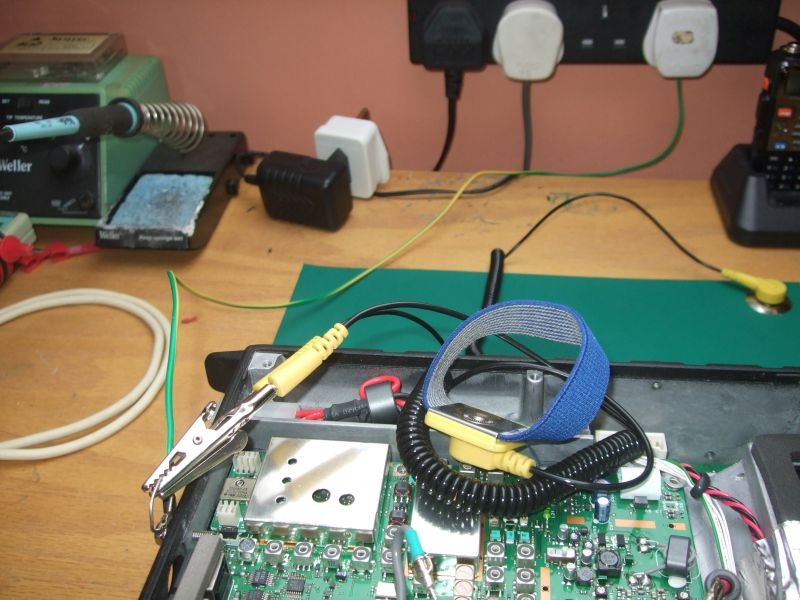
I have an earthing plug somewhere which is effectively a sealed plug with press studs on the back which are connected to the mains earth. Problem is I cant find it, it's probably in the same place as my original matting. Intermediate solution is a standard plug with a single wire from the earth pin running to a soldered on flat ring terminal. This is bolted directly to the earth terminal on the transceiver along with a wire loop to provide a common earth point, you can see that my wrist strap is connected here as well as the curly cable from the mat. Effectively the chassis on the transceiver is acting as a temporary bus bar for the system.
Once this was in place it was safe to remove the board. It is secured with about 12 machine screws around the edges and 4 more in the middle of the board a further 2 secure a couple of semiconductors mounted on the board to their cooling pads moulded on the chassis at each side of the board. A few connectors, a couple of miniature coaxial connectors and a ribbon lead disconnected and the board was out.
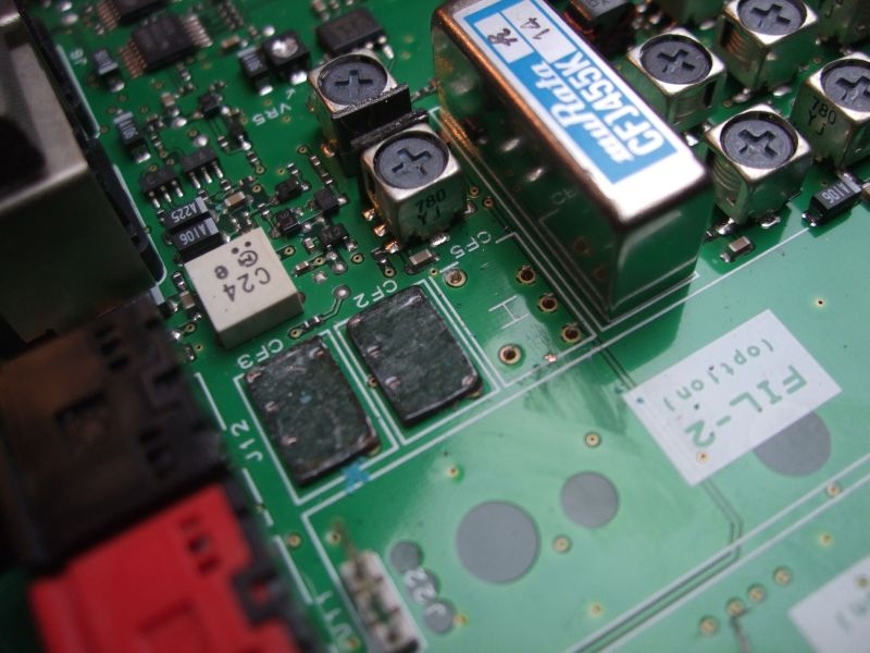
The recommended method of taking the filters out is to disassemble them from the top by breaking into the encapsulation and then removing the individual ceramic and mica insulation plates. Here they are with the tops off you can see how they are constructed with interleaved ceramic and dividing plates, these are sandwiched in between the plates that connect to the pins of the device
Carefully away with a jewellers screwdriver and a pair of tweezers and all the intermediary plates are out just leaving the connector plates and the bases.
As the plates are quite large in relation to the actual through board pins they will conduct a lot of heat away when trying to desolder so it is recommended that you snap the plates off from the pins below by gentle bending and twisting. This then allows you to remove the plastic base of the filter. This just leaves the pins which are soldered in plated through holes.
Later note.... this actually turned out to be bum information and caused untold grief with removal of the remnants of the pins and clearing the solder from the plated through holes.
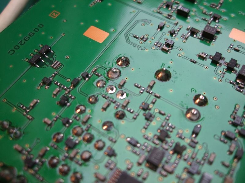
Here is the other side of the board showing a great number of surface mount components, many in very close proximity to the solder pads for the filter legs. To give some indication of scale the solder pads for through the board components are about 2mm, you can see that a lot of the surface mount components (the small rectangular blocks with silver ends) are much smaller than the pads so desoldering on the pads has to be done very carefully. It's a case of heating the target pad enough to remove the solder without overheating the adjacent surface mount components.
This where I ran into a problem I have a Weller digital soldering station that has bits down to 1mm but my smallest mini desoldering pump is too large to get into the pads properly. I have a complete Weller Vac desoldering station which also has bits down to 1mm but It had not seen the light of day for about 15 years. No real use for it when I gave up component level microprocessor repairs, I know also that the main desoldering head had been damaged in transit in my last equipment move.
Worth having a look though so I dug it out of the loft. It was as I had remembered, the head was physically damaged but it looked like nothing that could not be repaired with a bit of araldite. I plugged in the compressor base station and connected the head unit up. I has an electrical connection on a DIN plug and socket for the 24Vac feed and the temperature sensing feedback and a separate rubber pipe for connecting the head to the pump. The vacuum pump is started by a press button on the side of the handle and when operated the pump and it's pressure gauge operated without a problem. Trouble was the iron was stone cold regardless of the temperature setting. I pulled it apart suspecting that the damage to the head may have extended to the internal connection board for the thermostat, heating element and switch but that was not the case, the element itself is the problem. So I have an Vac desoldering station that sucks but won't get hot. I cant get an element for it as the head is now discontinued, I can get a replacement compatible head unit but it will cost me the best part of £150. I only want to desolder 9 holes! I may at some point look for a reasonably priced original replacement on Ebay.
In the short term I need a solution so to that end I have purchased a cheap combination desoldering tool. This consists of a 40W soldering Iron with an integral plunger desoldering pump built in.
The problem here is that the hole in the tip of this unit is HUGE, about 3mm in diameter and the tip itself too wide to do the job. I think I need the services of an engineering type bloke who could maybe modify the existing tip to allow me to use the 1mm tips from my £800 whiz bang desoldering kit which wont warm up?
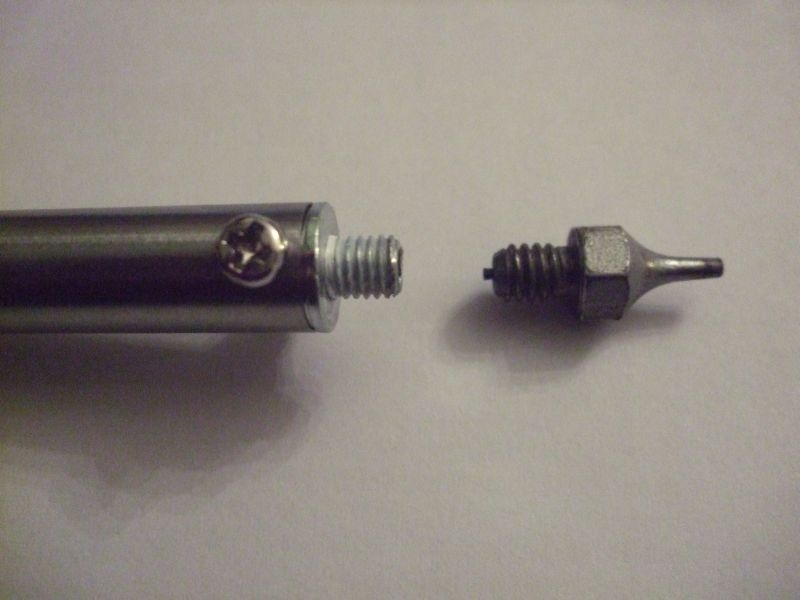
The end of the el cheapo iron screws out leaving a female on the bottom and a screw on the end of the iron, all the miniature tips from my other kit have screw connections with male threads on the bottom of them. It needs the cheapo tip modifying with a matching tapped hole in the end. This way I could attach any of the small tips I have to the cheapo iron, here it is in pictures.
Iron with partially screwed out tip and miniature vac tip
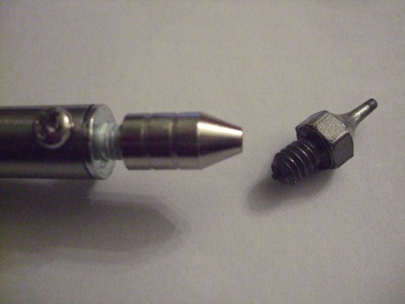
Or I need to attach this to this with a suitably tapped replacement connector, the threads are different on the iron and the mini tip.
First of all here is the transceiver on the bench, just to refresh the memory this is a multimode HF/VHF transceiver with general coverage receiver.
Here again with the lid off showing a better view of the top panel which is the one we are interested in.
Here are the Ceramic IF Filters which are the cause of the insensitivity on the VHF bands, three filters in all for 6KHz, 9KHz and 12KHz. You can see the salts caused by moisture within the plastic encapsulation leeching to the surface. Two look to be severely damaged, the third looks reasonably OK. The moisture essentially destroys the insulation and corrodes the plates within the filters rendering them useless, severely attenuating the IF (Intermediate Frequency) stages of the receiver, these particular filters are only relevant to the VHF section of the receiver.
Here are the replacements that I got from Technofix via their Ebay shop, just realised I didn't take them out of the bag, I'll put a better picture up when I fit them.
I did not want to start proper disassembly until I had the anti-static matting and a proper earth environment to work from. Here is the mat it's 400 x 300mm and is a nice fit from front to back on the bench.
The mat is conductive rubber of some type, it's black on the back. The press stud connector is supplied loose so that you can fit it wherever you want on the mat, I connected mine in the back corner. The prongs are bent down and pushed through the mat from the top then opened up on the bottom effectively gripping both surfaces of the mat. Press stud, curly cable and crocodile clip to connect to your earthing point.
I have an earthing plug somewhere which is effectively a sealed plug with press studs on the back which are connected to the mains earth. Problem is I cant find it, it's probably in the same place as my original matting. Intermediate solution is a standard plug with a single wire from the earth pin running to a soldered on flat ring terminal. This is bolted directly to the earth terminal on the transceiver along with a wire loop to provide a common earth point, you can see that my wrist strap is connected here as well as the curly cable from the mat. Effectively the chassis on the transceiver is acting as a temporary bus bar for the system.
Once this was in place it was safe to remove the board. It is secured with about 12 machine screws around the edges and 4 more in the middle of the board a further 2 secure a couple of semiconductors mounted on the board to their cooling pads moulded on the chassis at each side of the board. A few connectors, a couple of miniature coaxial connectors and a ribbon lead disconnected and the board was out.
The recommended method of taking the filters out is to disassemble them from the top by breaking into the encapsulation and then removing the individual ceramic and mica insulation plates. Here they are with the tops off you can see how they are constructed with interleaved ceramic and dividing plates, these are sandwiched in between the plates that connect to the pins of the device
Carefully away with a jewellers screwdriver and a pair of tweezers and all the intermediary plates are out just leaving the connector plates and the bases.
As the plates are quite large in relation to the actual through board pins they will conduct a lot of heat away when trying to desolder so it is recommended that you snap the plates off from the pins below by gentle bending and twisting. This then allows you to remove the plastic base of the filter. This just leaves the pins which are soldered in plated through holes.
Later note.... this actually turned out to be bum information and caused untold grief with removal of the remnants of the pins and clearing the solder from the plated through holes.
Here is the other side of the board showing a great number of surface mount components, many in very close proximity to the solder pads for the filter legs. To give some indication of scale the solder pads for through the board components are about 2mm, you can see that a lot of the surface mount components (the small rectangular blocks with silver ends) are much smaller than the pads so desoldering on the pads has to be done very carefully. It's a case of heating the target pad enough to remove the solder without overheating the adjacent surface mount components.
This where I ran into a problem I have a Weller digital soldering station that has bits down to 1mm but my smallest mini desoldering pump is too large to get into the pads properly. I have a complete Weller Vac desoldering station which also has bits down to 1mm but It had not seen the light of day for about 15 years. No real use for it when I gave up component level microprocessor repairs, I know also that the main desoldering head had been damaged in transit in my last equipment move.
Worth having a look though so I dug it out of the loft. It was as I had remembered, the head was physically damaged but it looked like nothing that could not be repaired with a bit of araldite. I plugged in the compressor base station and connected the head unit up. I has an electrical connection on a DIN plug and socket for the 24Vac feed and the temperature sensing feedback and a separate rubber pipe for connecting the head to the pump. The vacuum pump is started by a press button on the side of the handle and when operated the pump and it's pressure gauge operated without a problem. Trouble was the iron was stone cold regardless of the temperature setting. I pulled it apart suspecting that the damage to the head may have extended to the internal connection board for the thermostat, heating element and switch but that was not the case, the element itself is the problem. So I have an Vac desoldering station that sucks but won't get hot. I cant get an element for it as the head is now discontinued, I can get a replacement compatible head unit but it will cost me the best part of £150. I only want to desolder 9 holes! I may at some point look for a reasonably priced original replacement on Ebay.
In the short term I need a solution so to that end I have purchased a cheap combination desoldering tool. This consists of a 40W soldering Iron with an integral plunger desoldering pump built in.
The problem here is that the hole in the tip of this unit is HUGE, about 3mm in diameter and the tip itself too wide to do the job. I think I need the services of an engineering type bloke who could maybe modify the existing tip to allow me to use the 1mm tips from my £800 whiz bang desoldering kit which wont warm up?
The end of the el cheapo iron screws out leaving a female on the bottom and a screw on the end of the iron, all the miniature tips from my other kit have screw connections with male threads on the bottom of them. It needs the cheapo tip modifying with a matching tapped hole in the end. This way I could attach any of the small tips I have to the cheapo iron, here it is in pictures.
Iron with partially screwed out tip and miniature vac tip
Or I need to attach this to this with a suitably tapped replacement connector, the threads are different on the iron and the mini tip.
Ian
-
Stanley
- Global Moderator
- Posts: 90321
- Joined: 23 Jan 2012, 12:01
- Location: Barnoldswick. Nearer to Heaven than Gloria.
Re: Amateur Radio Homebrew (Shack Culture)
Or just bore the 2mm out to take the small tip with the thread turned off and Araldite it in? You know where I am.....
Stanley Challenger Graham
Stanley's View
scg1936 at talktalk.net
"Beware of certitude" (Jimmy Reid)
The floggings will continue until morale improves!
Stanley's View
scg1936 at talktalk.net
"Beware of certitude" (Jimmy Reid)
The floggings will continue until morale improves!