Amateur Radio Homebrew (Shack Culture)

User avatar
Stanley
Global Moderator
Global Moderator
Posts: 90301
Joined: 23 Jan 2012, 12:01
Location: Barnoldswick. Nearer to Heaven than Gloria.

Re: Amateur Radio Homebrew (Shack Culture)

Post by Stanley »

Image

I've found that transformer at last! It's a heavy little bugger. Let me know if you want it as it has to go....
Stanley Challenger Graham
Stanley's View
scg1936 at talktalk.net

"Beware of certitude" (Jimmy Reid)
The floggings will continue until morale improves!
User avatar
PanBiker
Site Administrator
Site Administrator
Posts: 16447
Joined: 23 Jan 2012, 13:07
Location: Barnoldswick - In the West Riding of Yorkshire, always was, always will be.

Re: Amateur Radio Homebrew (Shack Culture)

Post by PanBiker »

Looks Interesting Stanley, a nice big lump. Would need to have a 15v to 18v secondary and be capable of giving 20A or more to be useful for PSU use. Does it have any rating info on? I can pick it up at some point and recycle it if not suitable.
Ian
User avatar
Stanley
Global Moderator
Global Moderator
Posts: 90301
Joined: 23 Jan 2012, 12:01
Location: Barnoldswick. Nearer to Heaven than Gloria.

Re: Amateur Radio Homebrew (Shack Culture)

Post by Stanley »

Don't get technical with me! Just come round and take it away, if it's no good to you it might be OK for someone else. I forget what it came off but it was industrial grade....
Stanley Challenger Graham
Stanley's View
scg1936 at talktalk.net

"Beware of certitude" (Jimmy Reid)
The floggings will continue until morale improves!
User avatar
PanBiker
Site Administrator
Site Administrator
Posts: 16447
Joined: 23 Jan 2012, 13:07
Location: Barnoldswick - In the West Riding of Yorkshire, always was, always will be.

Re: Amateur Radio Homebrew (Shack Culture)

Post by PanBiker »

Made a start on the PSU refurbishment. I am following the modifications developed by Dutch radio amateur PA0FRI. Here is a schematic of the EP-925 PSU by PA0FRI (Frits).

Image

If you look at the internal layout of the PSU you will see that this is not the best thought out design. The fan is at the back whereas the heat sink it is meant to cool is mounted towards the front of the enclosure with the mass of the mains transformer in-between.

Image


The additional error in the design is that the fan only cuts in when the temperature of the heat sink rises and then it is an all or nothing circuit that drives the fan at full speed until the temperature drops again. This makes the power supply quite noisy under high load conditions. The heat sink has the main bridge rectifier and output pass transistors mounted on it, these are high power metal encased transistors which can generate quite bit of heat when under full load conditions.

The fan assembly is a standard 12v case mounted unit similar to what you would find in a computer PSU. It is fed via a simple driver transistor arrangement with a thermistor (thermal resistor) acting as a thermostat in the circuit which is fitted to the heat sink to monitor the temperature. Under normal (cold) conditions the thermistor which is a PTC (positive temperature coefficient) device exhibits no or extremely low resistance so no current flows through the driver transistor and the fan is stationary. As the heat increases so does the temperature of the PTC and its resistance, this turns on the drive transistor which supplies current to the fan. The resistance goes from low to high quite quickly hence the all or nothing action of the fan.

A simple modification of adding a small amount of resistance in series with thermistor will have the effect of running the fan all the time but at a slower speed. This keeps the heat sink much cooler as air is circulating all the time, the original action of the circuit is not affected and it will still drive to full speed should the heat continue to rise. Extended tests show that this simple modification has a dramatic effect on the overall performance of the cooling circuit. Here is a closer view of that portion of the heat sink.

Image


I have added a 1.8K resistor in series with the thermistor and the fan now runs permanently but quietly at about 20% of full speed.

Another view of the top of the full heat sink assembly. The complete assembly is actually two heat sinks mounted on top of each other with spacers. The bottom level has three pass transistors and voltage regulator, the top holds two more pass transistors, bridge rectifier assembly and the heat sensing thermistor.

Image


Modification two will be to upgrade the bridge rectifier assembly. The one fitted as standard to the PSU is a 25A device which is the rated value of the PSU so it is working at full capacity and as such liable to failure under high load conditions. Working at or near the rated value will generate more heat as well so increasing the rating here by introducing a bit of overkill will bear dividends in two areas of overall performance.

I will order up a replacement bridge rated at 50A and some heat sink compound for mounting the new component.

I have added some desktop lighting to the bench in the shape of an adjustable illuminated magnifying lamp which should make my construction projects somewhat easier on the eyes.

More to follow.
Ian
User avatar
Stanley
Global Moderator
Global Moderator
Posts: 90301
Joined: 23 Jan 2012, 12:01
Location: Barnoldswick. Nearer to Heaven than Gloria.

Re: Amateur Radio Homebrew (Shack Culture)

Post by Stanley »

Very neat and tidy, impressive!
Stanley Challenger Graham
Stanley's View
scg1936 at talktalk.net

"Beware of certitude" (Jimmy Reid)
The floggings will continue until morale improves!
User avatar
PanBiker
Site Administrator
Site Administrator
Posts: 16447
Joined: 23 Jan 2012, 13:07
Location: Barnoldswick - In the West Riding of Yorkshire, always was, always will be.

Re: Amateur Radio Homebrew (Shack Culture)

Post by PanBiker »

New 50A bridge rectifier came the day after I ordered it from CPC. The rectifier is secured to the heat sink with a single centre nut and bolt with plain and lock washers top and bottom. The AC input leads are soldered directly to the rectifier via heavy gauge stranded cable on short leads from the secondary winding of the transformer. The output leads from the rectifier are on push blade connectors so easily removed. I used my 100w Weller instant heat gun to get the input leads off.

Image


Here's the heat sink after the old rectifier has been removed. You can see I have taped the blade connectors taken from the output of the rectifier. This is because these two leads are connected at the other end to the main smoothing capacitor for the output of the PSU. It's a large value capacitor and as such, even with the supply switched off and disconnected can store a hefty charge, not one you want to stick your fingers on.

Image


Here are the old and new rectifiers side by side, same physical size but at 50A, twice the current handling capability from the replacement. You can see that the old device has four small capacitors connected between the four terminals of the bridge. These are 100nf (0.1uF) ceramic disc capacitors and are fitted to suppress residual oscillation currents which may flow in the diodes in the bridge. These residual currents could manifest as electrical noise on the output lines of the PSU. The leads on the original capacitors were well wrapped around the terminals and then flow soldered. Not easy to remove without damaging them, the discs are only about a quarter inch across. I elected to replace these rather than try to remove and took the opportunity to upgrade the voltage rating slightly with the replacements.

Image


Servisol heat sink compound, used for creating a thermal conduction layer between the component and the heat sink, smooths out any imperfections in the two metal surfaces.

Image


All reassembled but just reviewing this image I can see that I mounted the central fixing bolt through the wrong hole when reassembling. Looking at the photo with the bridge removed I can see there are two relatively close together as the heat sink looks like it was pre drilled for power transistor mounting. It's no real problem, It's electrically and thermally sound, I'll try not to let my mild OCD get in the way and vex too much about this, (it was a bit of a bugger getting the bolt back up through the hole in the first place).

Image


First run up, I have the meter attached to the low current output terminals, the big ones to the left are the high current terminals for connecting loads up to the maximum rating of the PSU. I have not really replaced anything that would have a direct effect on the output voltage. Just a check for functionality, the adjustment potentiometer allows me to set it to 13.8v which is the nominal voltage required by my station equipment, this based on the same voltage give by an average car battery when in use. I have swapped it out for the switched mode supply I used before and can already see that it is considerably quieter from an RFI point of view when in receive mode on my transceivers.
Ian
User avatar
Stanley
Global Moderator
Global Moderator
Posts: 90301
Joined: 23 Jan 2012, 12:01
Location: Barnoldswick. Nearer to Heaven than Gloria.

Re: Amateur Radio Homebrew (Shack Culture)

Post by Stanley »

As usual, it all goes over my head but I know a job when I see it. I'm surprised you left the fixing bolt in the wrong hole. Dear me..... :grin:
Stanley Challenger Graham
Stanley's View
scg1936 at talktalk.net

"Beware of certitude" (Jimmy Reid)
The floggings will continue until morale improves!
User avatar
PanBiker
Site Administrator
Site Administrator
Posts: 16447
Joined: 23 Jan 2012, 13:07
Location: Barnoldswick - In the West Riding of Yorkshire, always was, always will be.

Re: Amateur Radio Homebrew (Shack Culture)

Post by PanBiker »

I can move on now to the ground tuner project. I have all the components and will be making a start shortly. I'll post my progress as I go.
Ian
User avatar
PanBiker
Site Administrator
Site Administrator
Posts: 16447
Joined: 23 Jan 2012, 13:07
Location: Barnoldswick - In the West Riding of Yorkshire, always was, always will be.

Re: Amateur Radio Homebrew (Shack Culture)

Post by PanBiker »

Decided to make a start on the ground tuner. As I need all the major components so that I can plan the layout within the chassis I decided to start with manufacturing the coil. This will eventually end up as a tapped coil. The design is air spaced and is 13 turns on a 37mm former using 2mm (14swg) ECW. Once the coil is wound it will need some form of central support and method of mounting to allow isolation of the coil from the chassis. The simplest way to do this is to use a flat former to support the coils made from some form of insulating material. I ordered a sheet of 2mm perspex for this purpose. Here it is with a 40mm strip cut from the main sheet.

Image

The finished coil will be about 40mm - 50mm long so I cut the 40mm strip into two 105mm lengths, spare will be useful in case I make a mistake on making the former.

Image

I hunted around a bit for something of the correct diameter to wind the coil on and eventually found that the small jars that herbs and spices are supplied in are exactly 37mm diameter so just the job for what is needed.

13 turns of ECW on a 37mm former requires just over 1.5m of wire. I cut this length off the reel that I bought via Ebay and spent a while straightening it out as at this gauge it does not come off the small reel its supplied on without one or two kinks. The coil is wound close spaced and then each coil is pulled out slightly to create about 3mm - 5mm spacing. Here it is wound onto the spice jar former. I have taped the ends to anchor them during winding and to hold it in place until transferred to its support former.

Image


I marked up the support former working from a vertical division line in the middle with 6 verticals each side spaced 5mm apart. I used a small round file to notch out top and bottom, these notches will hold each of the coils in place. I have filed down about 1.5mm along each edge so this should allow the 37mm diameter coils to sit nicely in the grooves. Here it is marked up on the protection film and filed up along each edge.

Image

Here is the finished centre former with its protective films removed.

Image

One or two holes to be drilled in this yet for terminating each end of the coil and for attaching small mounting brackets. Once this assembly is finished I will be able to plan the layout on the chassis.
Ian
User avatar
Stanley
Global Moderator
Global Moderator
Posts: 90301
Joined: 23 Jan 2012, 12:01
Location: Barnoldswick. Nearer to Heaven than Gloria.

Re: Amateur Radio Homebrew (Shack Culture)

Post by Stanley »

Nice job but why didn't you give me a shout? I could have turned you a core up and threaded it....
Stanley Challenger Graham
Stanley's View
scg1936 at talktalk.net

"Beware of certitude" (Jimmy Reid)
The floggings will continue until morale improves!
User avatar
PanBiker
Site Administrator
Site Administrator
Posts: 16447
Joined: 23 Jan 2012, 13:07
Location: Barnoldswick - In the West Riding of Yorkshire, always was, always will be.

Re: Amateur Radio Homebrew (Shack Culture)

Post by PanBiker »

I have to tap the coil at 12 points to create the variable inductor. A solid core would be neat when wound but not as easy to solder 1.5mm tapping wires to without making a mess of it. A small roller inductor would probably do the job as well but would be overkill for what is required. The design calls for air spacing, it would be possible with this gauge of wire to suspend it between pillars but this is the easiest and next best thing without a lathe and is a common method of support. Thanks for the offer anyway.
Ian
User avatar
PanBiker
Site Administrator
Site Administrator
Posts: 16447
Joined: 23 Jan 2012, 13:07
Location: Barnoldswick - In the West Riding of Yorkshire, always was, always will be.

Re: Amateur Radio Homebrew (Shack Culture)

Post by PanBiker »

Continued with the coil assembly today. When I first transferred it onto the former I found that the locating grooves were not deep enough to hold each of the coils in place when tensioned. I ran the file over them all again to nearly 2mm depth. Nock on effect of this was that the preformed coils were then slightly too large for the former so I had to fix on one end of the coil and than chase the rest around the former to take up the slight slack. No real problem but I ended up with nearly an extra turn which again isn't a problem to the design. I did have to make a couple of more notches top and bottom though to accommodate the extra turn. The coils are held under tension so I temporarily pegged the ends with plastic mounting pillars after crimping on the 2mm entry ring connectors.

Here it is mounted up and temporarily pegged.

Image

Next job was to replace the plastic pegs with it's mounting bolts. I have used flanged screws and matching flanged nuts, these have serrated faces so will make a good electrical contact. There will be other connections to these points. I cut a 10mm strip from some spare aluminium sheet and made a couple of brackets for mounting the coil. I will raise the coil and insulate it from the chassis with a strip of perspex underneath when it is finally mounted.

Here is the finished coil assembly.

Image


I have mounted it on a temporary wood base to hold it firm so that I can remove the enamelling on the top of each turn to create the tapping points. The observant will see that there appears to be 14 coils when I only need 12. There is actually 12 full turns and a half turn at each end, I will only tap the centre 12 along the top, the extra half turn at each end will have no appreciable effect on the operation of the tuner as the inductance at each tap is a simple trade off with the variable capacitor within the design.

I have started on the front escutcheon of the cabinet by fitting it's new aluminium face as the next job when positioning the components within the chassis will be to determine the drilling points for the components that mount on or through the front fascia. I have to position the meter movement, variable capacitor, 12 way rotary switch assembly and a variable resistor used for setting the sensitivity of the meter.. The front escutcheon is an irregular shape at the back so after mounting the new front plate I have scribed round the periphery from the back and will set the centre line for the meter cut out, switch and variable capacitor. I have flanged knobs for the switch and variable capacitor so they need to be on the centre line, the meter adjust potentiometer can be offset if required.
Ian
User avatar
Stanley
Global Moderator
Global Moderator
Posts: 90301
Joined: 23 Jan 2012, 12:01
Location: Barnoldswick. Nearer to Heaven than Gloria.

Re: Amateur Radio Homebrew (Shack Culture)

Post by Stanley »

As usual, a tidy job Ian......
Stanley Challenger Graham
Stanley's View
scg1936 at talktalk.net

"Beware of certitude" (Jimmy Reid)
The floggings will continue until morale improves!
User avatar
PanBiker
Site Administrator
Site Administrator
Posts: 16447
Joined: 23 Jan 2012, 13:07
Location: Barnoldswick - In the West Riding of Yorkshire, always was, always will be.

Re: Amateur Radio Homebrew (Shack Culture)

Post by PanBiker »

I used a couple of strips of insulation tape to mask off the coils and create the areas for cleaning the enamel off for the tapping points, this should help to keep it a neat job.

Image

The interconnections including the tapping wires for the coil need to use 1.5mm insulated wire. I have a short length of twin and earth mains lighting cable which is ideal so have stripped this down and will use the brown and blue conductors. The wire is solid core so will easily form into nice rigid cable runs. The unit will develop quite high currents when in use hence the reasonably hefty specification for the internal wiring. I have set aside 12 x 200mm lengths for the coil tappings, I can't attach these yet as they will need to be wired sequentially to the 12 way switch once this is in place.

I made a start on front panel layout by positioning the meter and the two main adjustment knobs on the back of what will become the front panel. I have decided to put the meter at the left of the design, rotary switch in the middle and the variable capacitor on the right of the front panel. I can fit the meter adjust potentiometer at the side of the meter, it only needs a small adjustment knob so will not take a lot of room up on the front face.

Image


My next job will be to cut out the 50mm hole for the meter movement, this is the only component which is actually mounted directly on the front panel so it needs to be accurately aligned through the escutcheon.
Ian
User avatar
PanBiker
Site Administrator
Site Administrator
Posts: 16447
Joined: 23 Jan 2012, 13:07
Location: Barnoldswick - In the West Riding of Yorkshire, always was, always will be.

Re: Amateur Radio Homebrew (Shack Culture)

Post by PanBiker »

In order to get the meter correctly located, I made a template for the main body cut out and the location of the fixing studs.

Image

I have no panel punch for this size of hole which needs to be just over 50mm diameter so I drilled round near the edge of the required cut out then used a junior hacksaw blade to join the holes together. A combination of flat, round and half round files finished of the main cut out. I used the template then to position the holes for the mounting studs. I drilled these slightly oversize so that there is a small amount of rotational adjustment on the movement so that I can fix it dead level on the front panel. You can see the line of the front escutcheon that I scribed onto the reverse of the front panel. The meter movement and stud fixings just fit in the space available. To the left of the meter you can see the centre line also scribed on the back. Variable capacitor and the 12 way switch will be aligned to this centre line.

Image

Here is the front panel view with the meter in place, the aluminium still has its protective film on although there is no real need to keep the surface pristine as I intend to fit coloured card onto the front face. This will carry any decals or lettering that the panel needs. The intention then is to finish the front panel with a thin perspex sheet which will provide a scratch proof finish. I have used this technique on some of my other construction projects and it works well. Doing this will also reduce how far the front of the meter movement protrudes from the face as I will cut and file a rectangular cut out for the meter face.

It's not clear on the photo but the left hand front fixing points for the front panel are clear of the edge of the meter movement although it does not look so with the angle that a took the photo from.

Image
Ian
User avatar
Stanley
Global Moderator
Global Moderator
Posts: 90301
Joined: 23 Jan 2012, 12:01
Location: Barnoldswick. Nearer to Heaven than Gloria.

Re: Amateur Radio Homebrew (Shack Culture)

Post by Stanley »

:grin:
Stanley Challenger Graham
Stanley's View
scg1936 at talktalk.net

"Beware of certitude" (Jimmy Reid)
The floggings will continue until morale improves!
User avatar
PanBiker
Site Administrator
Site Administrator
Posts: 16447
Joined: 23 Jan 2012, 13:07
Location: Barnoldswick - In the West Riding of Yorkshire, always was, always will be.

Re: Amateur Radio Homebrew (Shack Culture)

Post by PanBiker »

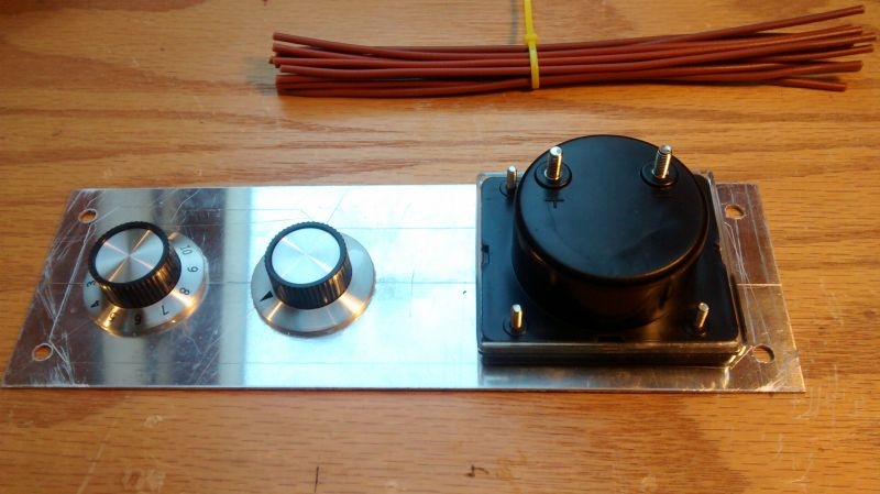
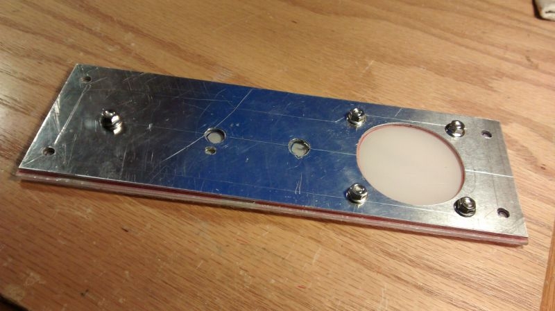
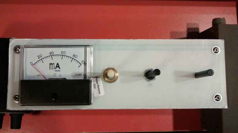
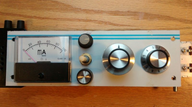
I drilled out the rest of the holes for the front mounted components and assembled to check the layout and alignment of the knob for the 12 way switch. I am leaning towards the flanged pointer knob for the switch and may well match that for the variable capacitor as the range is only through 180 degrees so the 1 to 10 would not really be relevant. I have two knobs for the meter adjust pot the lower would be more in keeping with the flanged although the one culled from the Pye Westminster may lend itself depending on which colour I choose for the front panel, these choices of course are not cast in stone. I am going to play around with some decals behind the main controls.

Image

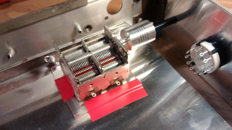
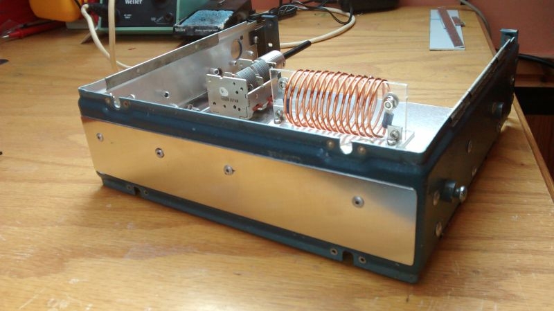
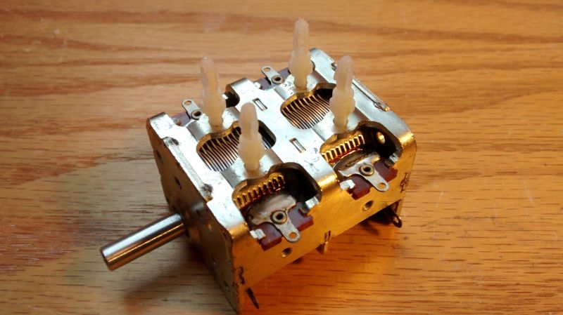
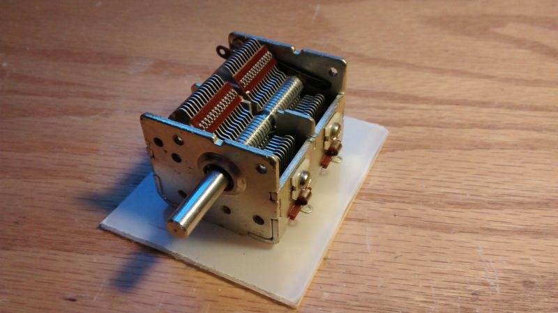
The next component to locate is the variable capacitor. This has to be insulated from the chassis, including its adjustment shaft. The capacitor has four threaded mounting holes on the bottom and I found these threaded plastic mounting pillars in the pot luck mixed bag of plastic bits I bought from the rally last year. They are chassis mount PCB supports.

Image

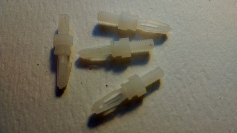
They have matching threads to the mounts on the capacitor. They will only need the pcb mount pillars snipping off and they will be perfect for the job.

Image

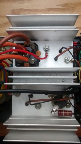
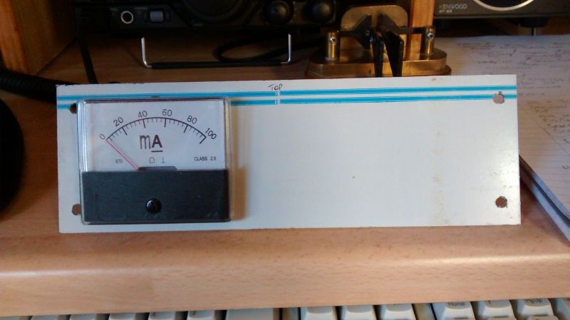
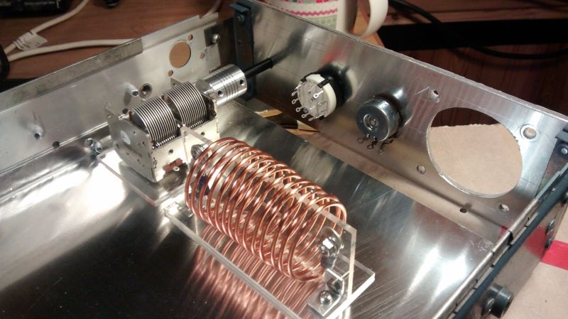
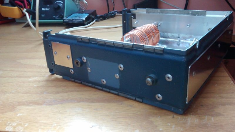
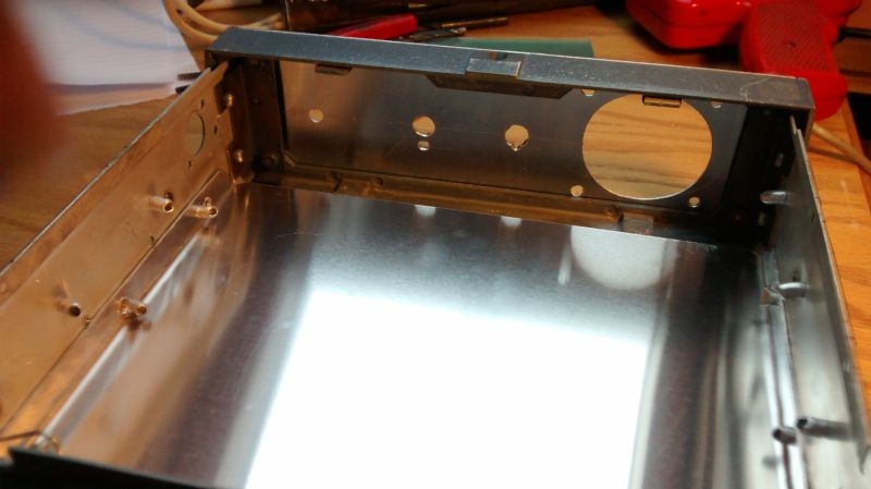
This is a view of the chassis from the back with front panel and escutcheon in place.

Image

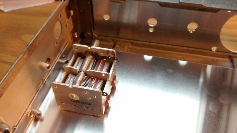
With the level that the chassis is set at and the hole for the capacitor shaft set on the centre line of the front panel the shaft is slightly low with regard to the centre line.

Image

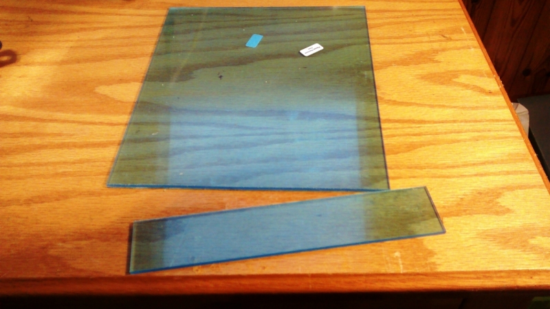
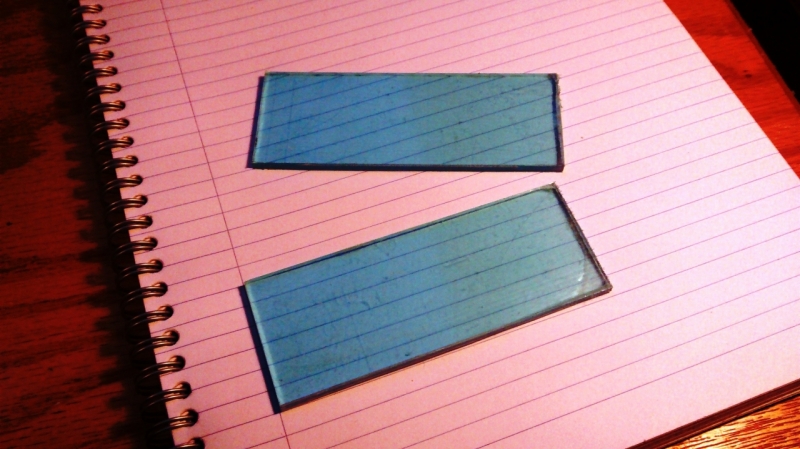
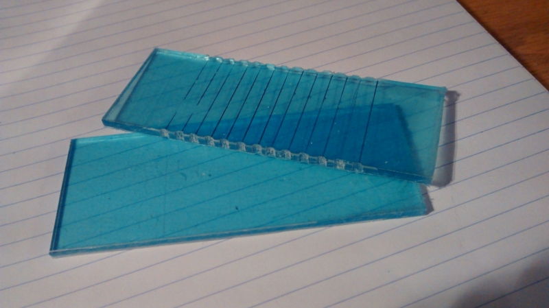
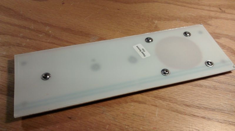
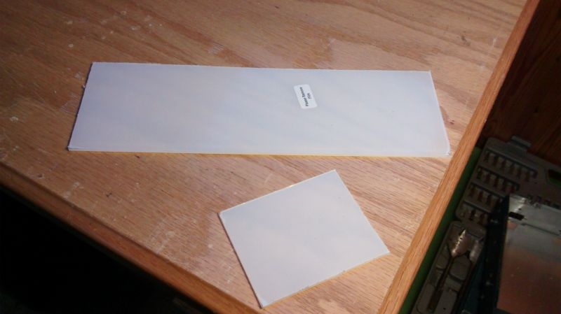
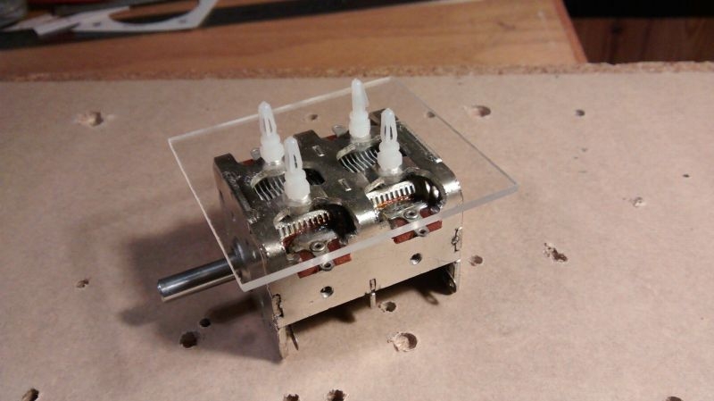
As the capacitor has to be isolated from the chassis, insulation will raise it to the exact level. The 1.2mm perspex that I have for the front escutcheon will serve as an insulated base for the capacitor. I have cut off a piece for the front panel and the off cut from the end will provide the base for the capacitor.

Image

Offering the capacitor up mounted on top of the perspex insulation brings the shaft perfectly in line with the hole on the centre line.

Image

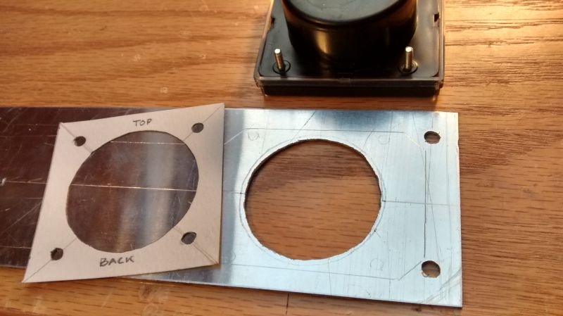
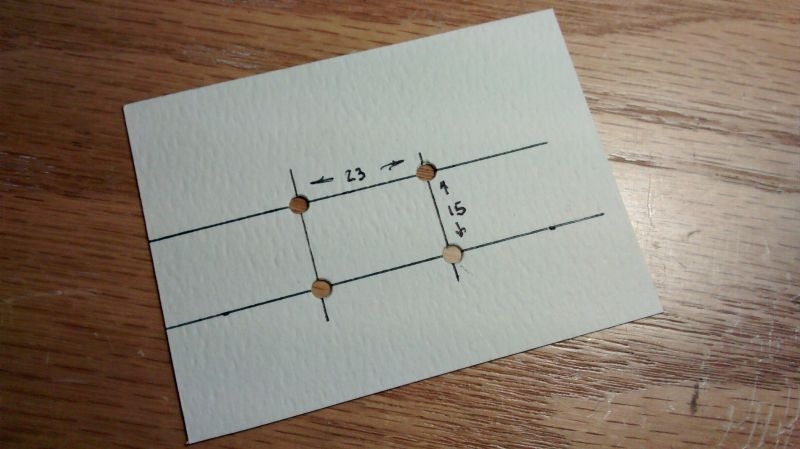
I made a template for the drilling points for the bottom of the capacitor.

Image

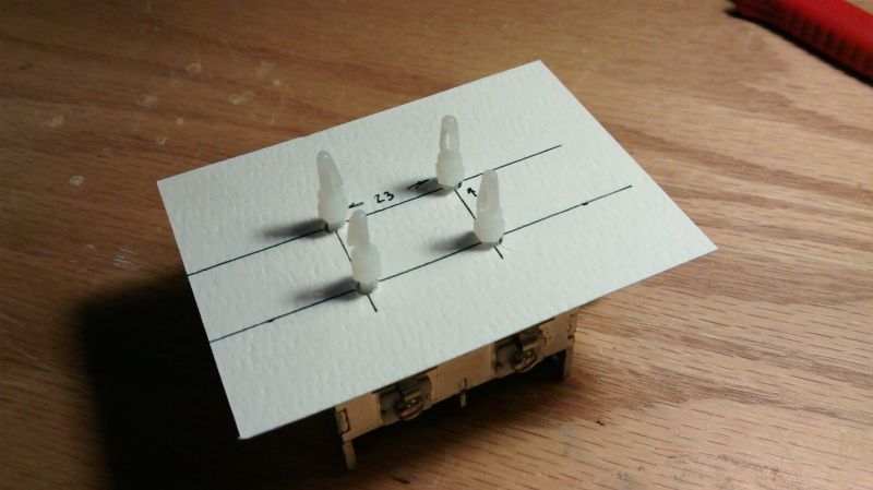
Here it is mounted to the bottom of the capacitor to check the alignment.

Image

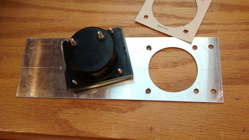
I transferred this to the perspex base, drilled out and checked by mounting to the capacitor.

Image

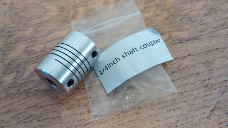
So, the bottom insulating mount is sorted. The capacitor will be set back on the chassis to allow sufficient room to insulate the metal shaft from the front panel. I found a long plastic shafted potentiometer at the rally that I can use to extend the capacitor shaft.

Image

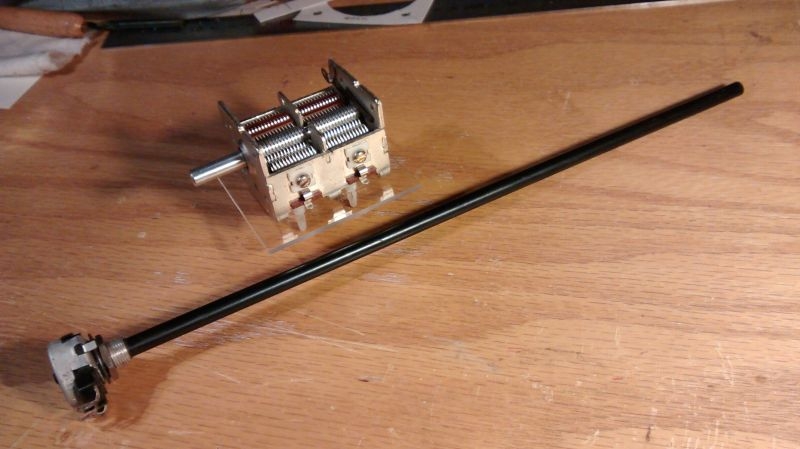
A bit of an optical illusion in the photo as the black plastic shaft looks a larger diameter to the metal shaft on the capacitor, they are both a quarter inch in reality.
Ian
User avatar
Stanley
Global Moderator
Global Moderator
Posts: 90301
Joined: 23 Jan 2012, 12:01
Location: Barnoldswick. Nearer to Heaven than Gloria.

Re: Amateur Radio Homebrew (Shack Culture)

Post by Stanley »

I don't understand it but I know nice tidy work when I see it.....
Stanley Challenger Graham
Stanley's View
scg1936 at talktalk.net

"Beware of certitude" (Jimmy Reid)
The floggings will continue until morale improves!
User avatar
PanBiker
Site Administrator
Site Administrator
Posts: 16447
Joined: 23 Jan 2012, 13:07
Location: Barnoldswick - In the West Riding of Yorkshire, always was, always will be.

Re: Amateur Radio Homebrew (Shack Culture)

Post by PanBiker »

Thanks Stanley, I haven't resprayed the case yet. I'm going to get all the component mounts sorted first then tidy the case up. I will only need to do the interconnections then. It's coming together but I have a way to go yet. A small toroid transformer to wind to sniff a bit of RF off to provide current drive for the meter, coil mount to the case and cabling to the switch, front screen, decals and perspex panel and then I can move on to the case, it has a few previous entry points on the back and a couple on the sides so I will have to make some blanking plates to tidy them up. Building to a pristine case is nice but I do like recycling the older stuff. I bet this old transceiver could tell a tale or two from its previous life.
Ian
User avatar
PanBiker
Site Administrator
Site Administrator
Posts: 16447
Joined: 23 Jan 2012, 13:07
Location: Barnoldswick - In the West Riding of Yorkshire, always was, always will be.

Re: Amateur Radio Homebrew (Shack Culture)

Post by PanBiker »

I can't drill out yet for positioning the variable capacitor until I have a 1/4" connector for joining the metal and plastic spindles. I though I had an insulating one but was mistaken, no worries, I have ordered a non insulated flexible coupler online this afternoon, they are not really expensive for the construction of them, it should come on Wednesday next week.

I have turned my attention to the small toroid transformer that is required. It's wound on a TO50-2 core and requires 24swg ECW for the secondary winding. I have this small inductor coil recovered from some redundant equipment, it has an iron core within the former and looks to be wound with good quality ECW of the right gauge, it will be near enough anyway for the job in hand.

Image

The toroid is wound with 20 turns reasonably evenly spaced. This is the secondary winding which will feed the meter movement to show peak current in the ground wire. The primary winding will consist of a short length of small diameter coax fed through the middle of the toroid just using the centre conductor, this will provide enough current from the tuned circuit to drive the meter. It will need a small diode acting as a rectifier and a smoothing capacitor to complete the meter circuitry. here is the toroid with its secondary winding.

Image

With that sorted, I have moved on to the front perspex panel which will need to be a copy of the aluminium front panel. I cut the 1.2mm perspex sheet slightly oversize and will file it down to get a matching edges. To aid in perfect alignment I have drilled out and bolted the perspex to the front panel, this will aid accurate drilling and filing to fit. I have only drilled through at the uncritical points at the moment as a means to an end, I can file these to final fit later.

Image

Reviewing the meter fixing I can see that the front bezel on the meter is stepped and will not really lend itself to sitting within a cut out rectangle in the perspex. I will replicate the 52mm hole and fit the meter conventionally through the perspex and aluminium front panel, the mounting studs are long enough to cater for this.

Image

Another pleasant hour and a half and a bit nearer pulling it together.
Ian
User avatar
Stanley
Global Moderator
Global Moderator
Posts: 90301
Joined: 23 Jan 2012, 12:01
Location: Barnoldswick. Nearer to Heaven than Gloria.

Re: Amateur Radio Homebrew (Shack Culture)

Post by Stanley »

:grin:
Stanley Challenger Graham
Stanley's View
scg1936 at talktalk.net

"Beware of certitude" (Jimmy Reid)
The floggings will continue until morale improves!
User avatar
PanBiker
Site Administrator
Site Administrator
Posts: 16447
Joined: 23 Jan 2012, 13:07
Location: Barnoldswick - In the West Riding of Yorkshire, always was, always will be.

Re: Amateur Radio Homebrew (Shack Culture)

Post by PanBiker »

I continued with the perspex front panel and filed and finished the edges which I had cut slightly oversize. Bolting it to the back panel and using this as a template was a good move. After filing the outside edges to size I finished them off with fine emery as these will be on show on the finished tuner. I drilled out the holes for the switch, variable capacitor shaft and the meter adjust potentiometer. The 52mm hole for the meter was started with a reasonable sized hole near the edge and then sawing out the rest within the edge of the existing hole in the backplate using a coping saw. All holes finished off with careful filing. Front panel is now complete and I temporary fixed all the components to check for clearances.

Image

I have cut a short length of the long plastic shaft from the variable resistor bought at the rally shown on the right of the image above. This will be used to extend and isolate the shaft of the variable capacitor. The shaft coupler I ordered has come. This is drilled out to accept 1/4" spindles and has two Allen Head grub screw fixings for each spindle fastening.

Image

Flexibility is built into the coupler by the spiral cut in the middle of the coupler which is cut right through to the centre bore. The cut is about 0.5mm width and the number of turns gives a reasonable amount of flexibility in the coupler. I don't know what the material cost are for something like this but the £3.50 I paid for it seems cheap for the amount of machining within the design, maybe Stanley will comment on this as it's more his line of expertise.
Ian
User avatar
PanBiker
Site Administrator
Site Administrator
Posts: 16447
Joined: 23 Jan 2012, 13:07
Location: Barnoldswick - In the West Riding of Yorkshire, always was, always will be.

Re: Amateur Radio Homebrew (Shack Culture)

Post by PanBiker »

With the shaft coupler in hand I could move on to mounting the variable capacitor to the chassis. With the insulation already drilled and the shaft coupler and its plastic extension in place it was just a case of locating the capacitor in the correct place on the chassis but there was a slight problem, how can I set the drilling points on the chassis for the four screw mounting points on the capacitor? It has to be located so that the shaft is in line with the hole through the front escutcheon so needs a reasonable degree of accuracy whilst working blind from the top. After a bit of thought I figured a solution, I first mounted the insulation to the bottom of the capacitor with its mounting screws and then attached two strips of insulation tape at the front and back to temporary secure the capacitor to the insulation. I could then remove the screws and position the capacitor and it's insulation mount where I needed it to align with the front panel. I then secured the perspex insulation to the chassis in the same way, the photo shows the method at this point.

Image

I then removed the tape temporarily securing the capacitor to the insulation which then gave me access to its mounting holes. I marked the drilling points, centre punched them and drilled them out from the top after removing the insulation. It worked a treat and I ended up with the capacitor in the correct place for shaft alignment through the front panel. Any small discrepancy will be countered by the flexible shaft coupler.

Next job was mounting the coil, I have drilled out another small piece of perspex to mount this on just to ensure that the coils are insulated from the chassis. The image shows the capacitor and coil assembly in their final mounting positions.

Image

One end of the coil will be attached to one side of the capacitor so I have aligned it accordingly so that I can keep the interconnecting lead lengths as short as possible.
Ian
User avatar
Stanley
Global Moderator
Global Moderator
Posts: 90301
Joined: 23 Jan 2012, 12:01
Location: Barnoldswick. Nearer to Heaven than Gloria.

Re: Amateur Radio Homebrew (Shack Culture)

Post by Stanley »

:grin:
Stanley Challenger Graham
Stanley's View
scg1936 at talktalk.net

"Beware of certitude" (Jimmy Reid)
The floggings will continue until morale improves!
User avatar
PanBiker
Site Administrator
Site Administrator
Posts: 16447
Joined: 23 Jan 2012, 13:07
Location: Barnoldswick - In the West Riding of Yorkshire, always was, always will be.

Re: Amateur Radio Homebrew (Shack Culture)

Post by PanBiker »

I'm at the stage now where I am ready to start the internal wiring so the case needs to be painted up. As the case is from a former Pye Westminster transceiver it has a number of holes in it from it's original sockets and connectors. There are a few more that have appeared as a result of replacing the chassis lower down in the frame rather than in its original position in the centre of the case. The case needs to be reasonably RF tight, there will be fairly high power RF currents across the internal components when in use. My transmitter can deliver 100W output to the antenna. The ground tuner when resonant will develop similar power in the artificial earth circuit that it produces. Stray RF fields leaking from equipment can play havoc if allowed to run wild in the station and can lead to RFI (Radio Frequency Interference) being generated and radiated.

I plugged the smaller holes by using pop rivets. The back had a number of cut outs in so it was easier to make a new plate to cover them all at once rather than individually. I riveted this utilising the old mounting holes for the centrally mounted chassis.

Image

The Westminster transceiver had a microphone socket on the side of the case near the front, I made another plate to blank this off and again utilised existing mounting holes as riveting points.

Image

The recycled case will not be particularly pretty but it will be functional. I have decided to paint it using black Hammerite as this will cover well and help to hide some of the lumps and bumps. Most of my equipment is black so it will fit in well and will be installed under my antenna matching unit. I will be fitting a coloured front to hold the decals.
Ian
Post Reply

Return to “Amateur Radio”