Amateur Radio Homebrew (Shack Culture)
-
PanBiker

- Site Administrator

- Posts: 16449
- Joined: 23 Jan 2012, 13:07
- Location: Barnoldswick - In the West Riding of Yorkshire, always was, always will be.
Re: Amateur Radio Homebrew (Shack Culture)
Can't further the project now until I have the square section boom. Although I can almost finish the elements off now. Best not glue the bushes on though or I won't get the elements through the boom. 
Ian
-
Stanley

- Global Moderator

- Posts: 90301
- Joined: 23 Jan 2012, 12:01
- Location: Barnoldswick. Nearer to Heaven than Gloria.
Re: Amateur Radio Homebrew (Shack Culture)
I realised I had forgotten your acrylic rod Ian, it's still in the lathe. Tell me what you want me to do with it. On the bench in the yard?
Stanley Challenger Graham
Stanley's View
scg1936 at talktalk.net
"Beware of certitude" (Jimmy Reid)
The floggings will continue until morale improves!
Stanley's View
scg1936 at talktalk.net
"Beware of certitude" (Jimmy Reid)
The floggings will continue until morale improves!
-
PanBiker
- Site Administrator
- Posts: 16449
- Joined: 23 Jan 2012, 13:07
- Location: Barnoldswick - In the West Riding of Yorkshire, always was, always will be.
Re: Amateur Radio Homebrew (Shack Culture)
I cant machine it myself Stanley so if it's any use to you keep it. If not, I'll collect it and keep it in my treasure chest. I have a length of smaller diameter stuff as well. 
Ian
-
Stanley
- Global Moderator
- Posts: 90301
- Joined: 23 Jan 2012, 12:01
- Location: Barnoldswick. Nearer to Heaven than Gloria.
Re: Amateur Radio Homebrew (Shack Culture)
I'll put it in the non ferocious treasure chest. If you need it you know where it is!
Stanley Challenger Graham
Stanley's View
scg1936 at talktalk.net
"Beware of certitude" (Jimmy Reid)
The floggings will continue until morale improves!
Stanley's View
scg1936 at talktalk.net
"Beware of certitude" (Jimmy Reid)
The floggings will continue until morale improves!
-
PanBiker
- Site Administrator
- Posts: 16449
- Joined: 23 Jan 2012, 13:07
- Location: Barnoldswick - In the West Riding of Yorkshire, always was, always will be.
Re: Amateur Radio Homebrew (Shack Culture)
Here are the bushes that Stanley sorted for me. I have done a little bit more to the elements of the antenna. I drilled the holes at each end of the tube sections so that the set screws could contact the inner sliding rods.
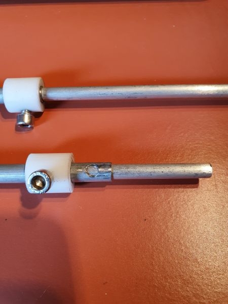
Both elements sorted and I reckon I made a reasonable job of getting all the set screws aligned. Not essential for the operation of the antenna but more pleasing for the aesthetics of the design.
I thought of gluing the bushes to the ends of the tube sections but have changed my mind. The Acetal bar used for the bushes is very smooth and would not be a good surface for bonding. I have deferred to the same method I used on the Moxon for securing and tidying up the element fixings. I have ordered some 19mm 3:1 adhesive lined heat shrink tubing and will use this to secure the bushes to prevent loss. I have some rubber grommets that will fit the tubing and butt up to the bushes before shrink wrapping them that will help smooth the sharp edge of the milled bush. I used the same method on the Moxon and it worked quite well.
Before I order the square boom section that I need I will check down the cellar that I don't have any remnants of the four 12 element Yagi antennas that my mate Bill and I built 30 years ago. They used square booms as well, I don't think there are any remains but I have just found one of the poles that we used to support them when we used them stacked and bayed up the side of the kitchen, it's worth checking first.
Both elements sorted and I reckon I made a reasonable job of getting all the set screws aligned.
I thought of gluing the bushes to the ends of the tube sections but have changed my mind. The Acetal bar used for the bushes is very smooth and would not be a good surface for bonding. I have deferred to the same method I used on the Moxon for securing and tidying up the element fixings. I have ordered some 19mm 3:1 adhesive lined heat shrink tubing and will use this to secure the bushes to prevent loss. I have some rubber grommets that will fit the tubing and butt up to the bushes before shrink wrapping them that will help smooth the sharp edge of the milled bush. I used the same method on the Moxon and it worked quite well.
Before I order the square boom section that I need I will check down the cellar that I don't have any remnants of the four 12 element Yagi antennas that my mate Bill and I built 30 years ago. They used square booms as well, I don't think there are any remains but I have just found one of the poles that we used to support them when we used them stacked and bayed up the side of the kitchen, it's worth checking first.
Ian
-
PanBiker
- Site Administrator
- Posts: 16449
- Joined: 23 Jan 2012, 13:07
- Location: Barnoldswick - In the West Riding of Yorkshire, always was, always will be.
Re: Amateur Radio Homebrew (Shack Culture)
First things first, I checked for any remnants of previous build Yagi antenna projects and I don't have any bits remaining. I have ordered a length of 1" box section aluminium for the boom. I was contemplating 19mm square but I am going to mount an SO 239 socket on the antenna so it will only need a patch lead to connect to the transceiver. The chassis sockets have a 1" square base so I need the boom width to support a bracket for the socket.
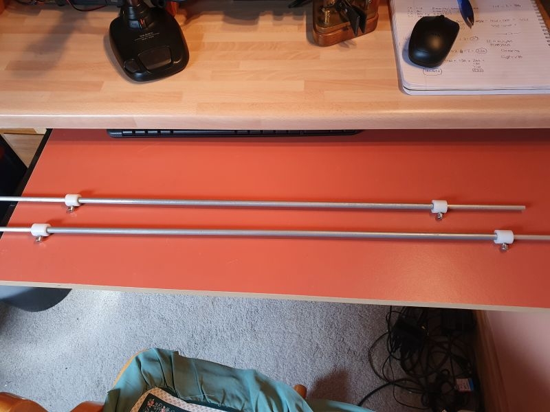
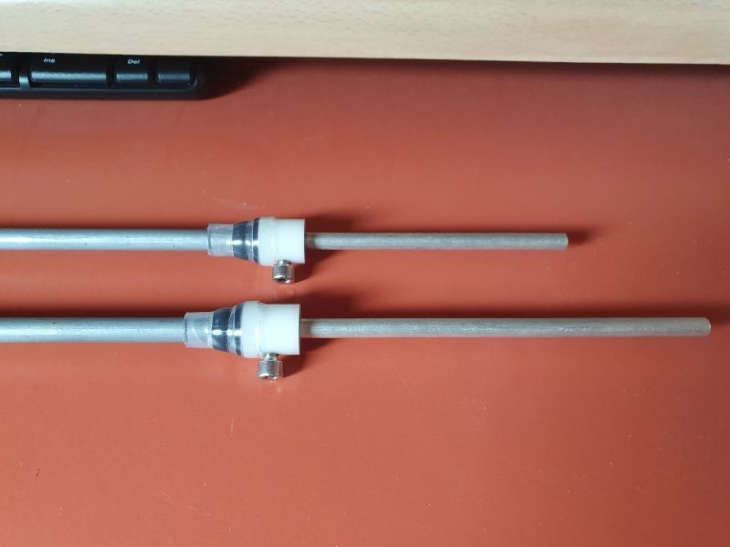
My 19mm adhesive lined heat shrink tubing arrived today two days ahead of schedule. Next photo shows how I have used it to secure the bushes to the centre sections of the elements. I had the tapered rubber grommets so put one of those on each. the 3:1 shrink ratio worked atreat. I have only done one end of each as the elements are secured through the boom rather than mounted on top. I will finalise the other ends once the elements are assembled to the boom.
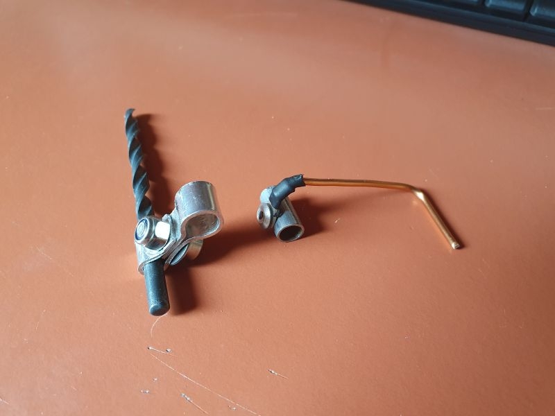
I have also been testing out ideas for potentially making the phasing link into an adjustable gamma match. That involves having an adjustable connection between the element and a smaller diameter phasing link. A gamma match would give a lot more control over the adjustments on the antenna. It also offers a way of interfacing the line to the element without making a fixed direct connection. The link would connect to the centre section of each element which is 8mm. I had thought of using 3mm aluminium bar for the phasing line. The left of the photo shows my effort of a folded aluminium slider. I made the 8mm bend first using a screwdriver shaft then a drill bit for the 3mm end. The 3mm is a good tight fit but I cant get the 8mm to pull up tight enough. Back to the drawing board.
The original design has a fixed phasing line spaced 5mm above the element and boom. I have a lot of adjustment available with the telescopic elements so I have deferred to the fixed phasing line idea. As we are working with aluminium which does not lend itself to easy soldering I have swapped to a smaller diameter line made from enamelled copper wire. I had to file it down a little bit to get a crimp connector on. I tested the idea by drilling an off-cut of tube and trying a pop rivet. I reckon this will be the method I use. I need to buy some slightly shorter rivets as the shortest I had were 10mm which is longer than the tube is in diameter. The method works well though and will give a good electrical connection.
My 19mm adhesive lined heat shrink tubing arrived today two days ahead of schedule. Next photo shows how I have used it to secure the bushes to the centre sections of the elements. I had the tapered rubber grommets so put one of those on each. the 3:1 shrink ratio worked atreat. I have only done one end of each as the elements are secured through the boom rather than mounted on top. I will finalise the other ends once the elements are assembled to the boom.
I have also been testing out ideas for potentially making the phasing link into an adjustable gamma match. That involves having an adjustable connection between the element and a smaller diameter phasing link. A gamma match would give a lot more control over the adjustments on the antenna. It also offers a way of interfacing the line to the element without making a fixed direct connection. The link would connect to the centre section of each element which is 8mm. I had thought of using 3mm aluminium bar for the phasing line. The left of the photo shows my effort of a folded aluminium slider. I made the 8mm bend first using a screwdriver shaft then a drill bit for the 3mm end. The 3mm is a good tight fit but I cant get the 8mm to pull up tight enough. Back to the drawing board.
The original design has a fixed phasing line spaced 5mm above the element and boom. I have a lot of adjustment available with the telescopic elements so I have deferred to the fixed phasing line idea. As we are working with aluminium which does not lend itself to easy soldering I have swapped to a smaller diameter line made from enamelled copper wire. I had to file it down a little bit to get a crimp connector on. I tested the idea by drilling an off-cut of tube and trying a pop rivet. I reckon this will be the method I use. I need to buy some slightly shorter rivets as the shortest I had were 10mm which is longer than the tube is in diameter. The method works well though and will give a good electrical connection.
Ian
-
Stanley
- Global Moderator
- Posts: 90301
- Joined: 23 Jan 2012, 12:01
- Location: Barnoldswick. Nearer to Heaven than Gloria.
Re: Amateur Radio Homebrew (Shack Culture)
I have quite a few rivets about Ian in iron, brass and aluminium. You could come and have a furtle.
Stanley Challenger Graham
Stanley's View
scg1936 at talktalk.net
"Beware of certitude" (Jimmy Reid)
The floggings will continue until morale improves!
Stanley's View
scg1936 at talktalk.net
"Beware of certitude" (Jimmy Reid)
The floggings will continue until morale improves!
-
PanBiker
- Site Administrator
- Posts: 16449
- Joined: 23 Jan 2012, 13:07
- Location: Barnoldswick - In the West Riding of Yorkshire, always was, always will be.
Re: Amateur Radio Homebrew (Shack Culture)
Thanks Stanley. One thing I have only just noticed and by accident is that the central section tubes are not aluminium! I was measuring with my tape and the magnetised tab at the end stuck to the tube! They must be some for of ferrous metal, treated as they don't rust and cleaned up with a quick rub with wire wool just like aluminium would. Makes no difference they are still conductive.
Looking at the aluminium slider again, I suppose it should have two screws, one to tighten each of the loops. Problem then is that it would alter the spacing too much between the element and the matching line. Reinforces my view that a fixed option is the best way forward.
Looking at the aluminium slider again, I suppose it should have two screws, one to tighten each of the loops. Problem then is that it would alter the spacing too much between the element and the matching line. Reinforces my view that a fixed option is the best way forward.
Ian
-
Stanley
- Global Moderator
- Posts: 90301
- Joined: 23 Jan 2012, 12:01
- Location: Barnoldswick. Nearer to Heaven than Gloria.
Re: Amateur Radio Homebrew (Shack Culture)
Stanley Challenger Graham
Stanley's View
scg1936 at talktalk.net
"Beware of certitude" (Jimmy Reid)
The floggings will continue until morale improves!
Stanley's View
scg1936 at talktalk.net
"Beware of certitude" (Jimmy Reid)
The floggings will continue until morale improves!
-
PanBiker
- Site Administrator
- Posts: 16449
- Joined: 23 Jan 2012, 13:07
- Location: Barnoldswick - In the West Riding of Yorkshire, always was, always will be.
Re: Amateur Radio Homebrew (Shack Culture)
Just had notification from Ebay that my box section aluminium for the boom has been posted. I should have it before Thursday this week.
Ian
-
PanBiker
- Site Administrator
- Posts: 16449
- Joined: 23 Jan 2012, 13:07
- Location: Barnoldswick - In the West Riding of Yorkshire, always was, always will be.
Re: Amateur Radio Homebrew (Shack Culture)
Delivered this morning so I can do a bit more assembly.
Ian
-
PanBiker
- Site Administrator
- Posts: 16449
- Joined: 23 Jan 2012, 13:07
- Location: Barnoldswick - In the West Riding of Yorkshire, always was, always will be.
Re: Amateur Radio Homebrew (Shack Culture)
Had an assembly session with the antenna yesterday. First job was to drill the boom for the elements. That done I fitted the shorter front element first, this is the director in place.
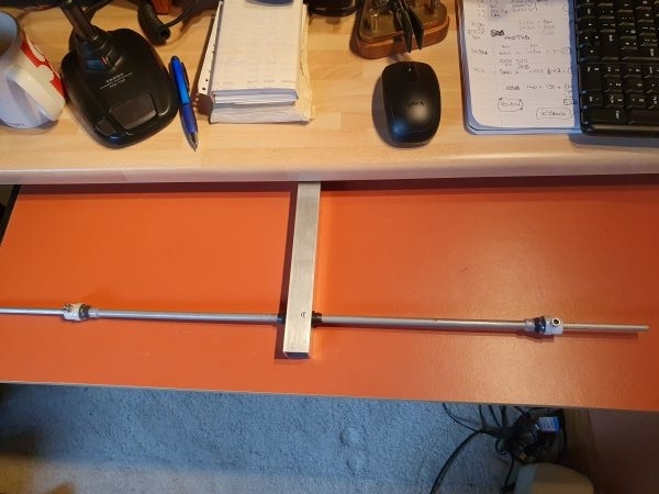
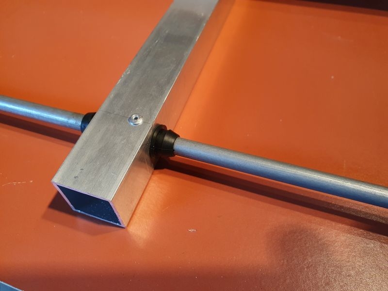
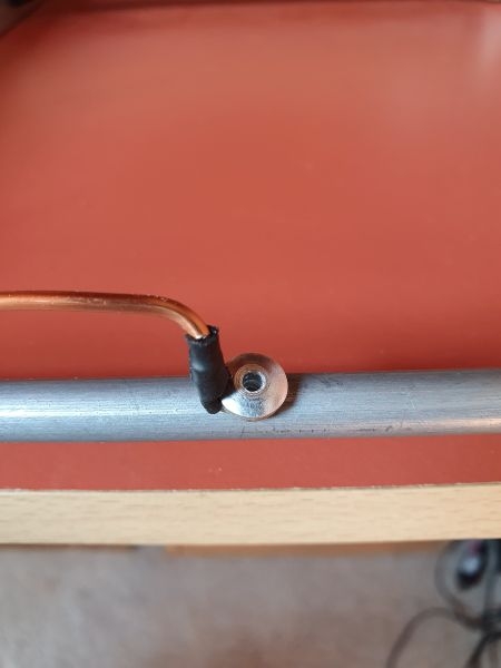
The next image shows the method of fixing the element to the boom. Once centralised, I drilled through the boom and into the element just right of centre. I used a pop rivet to secure the fixing. I repeated the drilling and riveting on the other side so the element is stabilised through the boom and securely fixed. I slid the rubber grommets on the elements butted up to the boom just to improve the look of the design.
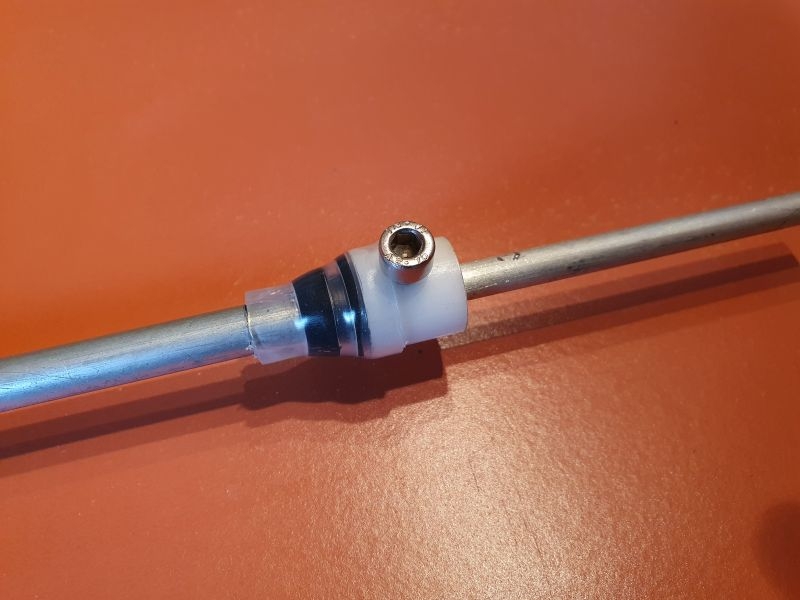
I finalised the ends of the elements with the bushes for the telescopic sections using self adhesive heat shrink to secure the bush to the central tube and hold the alignment of the screw hole through to the inner rod. More tapered grommets to give a smooth edge for the heat shrink.
Final image for yesterdays work shows the reflector element in place. You will see that there are two rivets on the top side, only one is securing the element on that side the other is to fill the hole that I drilled slightly wrong.
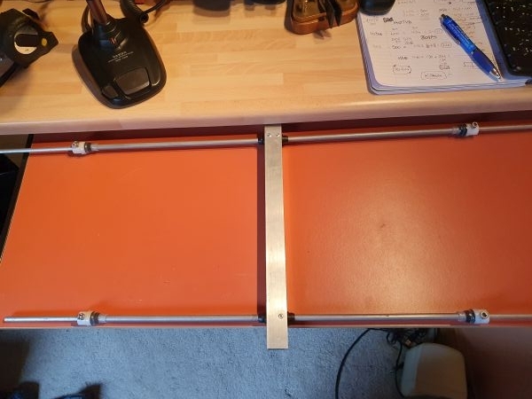
I had to do a bit of "fitting to get the elements level and square to one another in the boom. I don't have a pillar drill so I have to rely on measuring and drilling from both sides of the boom. I was a careful as I could be with the hand held drill but had to use a file to get the final fit. It's stil a few mm out but the discrepancy will not alter the efficiency especially as I have telescopic elements which should give a better range of adjustments. As Stanley says you will not notice from the top deck of the Ribble.
I drilled the holes in the elements at the correct distance on each element from the centre line ready to fit the phasing line, that's the next job.
The next image shows the method of fixing the element to the boom. Once centralised, I drilled through the boom and into the element just right of centre. I used a pop rivet to secure the fixing. I repeated the drilling and riveting on the other side so the element is stabilised through the boom and securely fixed. I slid the rubber grommets on the elements butted up to the boom just to improve the look of the design.
I finalised the ends of the elements with the bushes for the telescopic sections using self adhesive heat shrink to secure the bush to the central tube and hold the alignment of the screw hole through to the inner rod. More tapered grommets to give a smooth edge for the heat shrink.
Final image for yesterdays work shows the reflector element in place. You will see that there are two rivets on the top side, only one is securing the element on that side the other is to fill the hole that I drilled slightly wrong.
I had to do a bit of "fitting to get the elements level and square to one another in the boom. I don't have a pillar drill so I have to rely on measuring and drilling from both sides of the boom. I was a careful as I could be with the hand held drill but had to use a file to get the final fit. It's stil a few mm out but the discrepancy will not alter the efficiency especially as I have telescopic elements which should give a better range of adjustments. As Stanley says you will not notice from the top deck of the Ribble.
I drilled the holes in the elements at the correct distance on each element from the centre line ready to fit the phasing line, that's the next job.
Ian
-
PanBiker
- Site Administrator
- Posts: 16449
- Joined: 23 Jan 2012, 13:07
- Location: Barnoldswick - In the West Riding of Yorkshire, always was, always will be.
Re: Amateur Radio Homebrew (Shack Culture)
Todays job was to form and fit the phasing line to link the two elements. The HB9CV antenna design is effectively two driven dipoles, the front element director is shorter than the back reflector element, This efectively makes the antenna directional although both of the elements are driven.
In a conventional YAGI type antenna you only have one driven element with a parasitic reflector element behind and multiple parasitic director elements arranged in front along the boom. The more director elements you have in a design the greater the gain (or power increase) the antenna will have but the larger the length will be.
The phasing line in this design has to be fixed at nominally 5mm above the boom. In my plastic bits lucky bag I had some plastic support pillars that push fit and lock through a single hole. The top of the posts are threaded so that you can use them as spacers for PCB's and fix through to the posts. They are about 10mm high. I drilled a hole halfway up the plastic and threaded the enamelled copper wire used for the line through each one. I drilled and put four along the length of the boom.
Connection to the elements was done using crimp on ring connectors on the wire and then short pop rivets to the element. This is fine but not as tight as I would like it. A bit of weathering on the antenna and it may develop a high resistance at the connection point. As the centre tube is ferrous I think I might clean up around the fixing point and run some solder into the joint. The crimp connectors can be soldered and with a decent bit of heat I should be able to solder to the tube. That would certainly make a more mechanically and electrical sound joint.
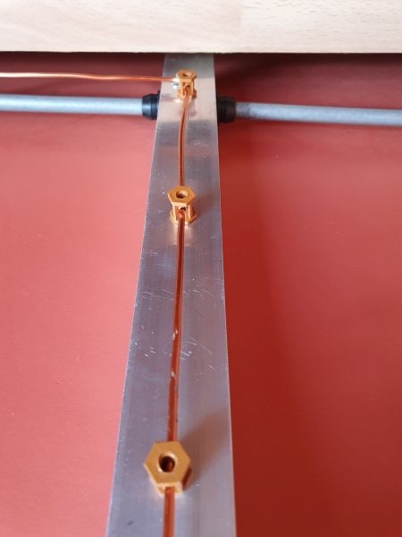
The next image shows the completed phasing line and the supports. The director element is at the top and the reflector element at the bottom. You can see that I have created a small loop on the 90 degree bend at the reflector element this was to take up a bit of slack in the length of the line and also create a good anchor point for connection to the SO 239 input socket. I made a small 90 degree bracket to support the socket. You will also see that I have run some Gorilla Epoxy adhesive round the bases of the support pillars. This is to stabilise the posts which makes the antenna a bit more robust.
I have a cranked Allen Key for the grub screw adjusters on the elements. That will fit nicely inside the boom for transportation. I have ordered a couple of square plastic end caps for each end of the boom which will finish it off nicely.
Not far off finished now. I need to get a bracket to clamp it to a mast, ideally one that can attach the antenna in horizontal or vertical orientation. I also have to fit a coupling capacitor between the input socked and the phasing line.
In a conventional YAGI type antenna you only have one driven element with a parasitic reflector element behind and multiple parasitic director elements arranged in front along the boom. The more director elements you have in a design the greater the gain (or power increase) the antenna will have but the larger the length will be.
The phasing line in this design has to be fixed at nominally 5mm above the boom. In my plastic bits lucky bag I had some plastic support pillars that push fit and lock through a single hole. The top of the posts are threaded so that you can use them as spacers for PCB's and fix through to the posts. They are about 10mm high. I drilled a hole halfway up the plastic and threaded the enamelled copper wire used for the line through each one. I drilled and put four along the length of the boom.
Connection to the elements was done using crimp on ring connectors on the wire and then short pop rivets to the element. This is fine but not as tight as I would like it. A bit of weathering on the antenna and it may develop a high resistance at the connection point. As the centre tube is ferrous I think I might clean up around the fixing point and run some solder into the joint. The crimp connectors can be soldered and with a decent bit of heat I should be able to solder to the tube. That would certainly make a more mechanically and electrical sound joint.
The next image shows the completed phasing line and the supports. The director element is at the top and the reflector element at the bottom. You can see that I have created a small loop on the 90 degree bend at the reflector element this was to take up a bit of slack in the length of the line and also create a good anchor point for connection to the SO 239 input socket. I made a small 90 degree bracket to support the socket. You will also see that I have run some Gorilla Epoxy adhesive round the bases of the support pillars. This is to stabilise the posts which makes the antenna a bit more robust.
I have a cranked Allen Key for the grub screw adjusters on the elements. That will fit nicely inside the boom for transportation. I have ordered a couple of square plastic end caps for each end of the boom which will finish it off nicely.
Not far off finished now. I need to get a bracket to clamp it to a mast, ideally one that can attach the antenna in horizontal or vertical orientation. I also have to fit a coupling capacitor between the input socked and the phasing line.
Ian
-
Stanley
- Global Moderator
- Posts: 90301
- Joined: 23 Jan 2012, 12:01
- Location: Barnoldswick. Nearer to Heaven than Gloria.
Re: Amateur Radio Homebrew (Shack Culture)
Tidy as usual... 
Stanley Challenger Graham
Stanley's View
scg1936 at talktalk.net
"Beware of certitude" (Jimmy Reid)
The floggings will continue until morale improves!
Stanley's View
scg1936 at talktalk.net
"Beware of certitude" (Jimmy Reid)
The floggings will continue until morale improves!
-
PanBiker
- Site Administrator
- Posts: 16449
- Joined: 23 Jan 2012, 13:07
- Location: Barnoldswick - In the West Riding of Yorkshire, always was, always will be.
Re: Amateur Radio Homebrew (Shack Culture)
I finished the bits off yesterday. I soldered the phasing harness connections at the elements and fitted a 39pF coupling capacitor and fired it up with my multimode 2m transceiver. I set the element lengths to what the design program gave for 144.300 MHz which is the calling frequency in the SSB portion of the band. Pleased to report that even hand held indoors it was almost a perfect match 1.2:1. I checked it 1MHz higher up in the band in the FM portion and it still metered out at a very acceptable 1.4:1. I reckon those readings will improve when mounted in the clear outside. My C58 multimode transceiver only puts out 1W so I need all the forward gain I can get. 
I'll see if I can get over the North Sea on sideband when I am up at Robin Hoods Bay with a nice high pressure area sitting on top of us. Could be good for tropospheric propagation. Nice take off from the site which is only a couple of hundred meters from the cliff tops.
I'll see if I can get over the North Sea on sideband when I am up at Robin Hoods Bay with a nice high pressure area sitting on top of us. Could be good for tropospheric propagation. Nice take off from the site which is only a couple of hundred meters from the cliff tops.
Ian
-
PanBiker
- Site Administrator
- Posts: 16449
- Joined: 23 Jan 2012, 13:07
- Location: Barnoldswick - In the West Riding of Yorkshire, always was, always will be.
Re: Amateur Radio Homebrew (Shack Culture)
There was one final job to do on the antenna and that was to fashion some kind of mount for fixing it to the mast. I opted for the easiest which is just a couple of holes through the boom and a U bolt arrangement. This was OK apart from the fact that I couldn't find a U bolt of the the right size in Barlick. I went to B&Q and they only had shorter versions that were unsuitable, cost an arm and a leg as well.
I opted to make my own so I got a length of 5mm threaded bar and I found some matching wing nuts to go with it. 1m of bar and 10 wing nuts were less than the price of one U bolt!
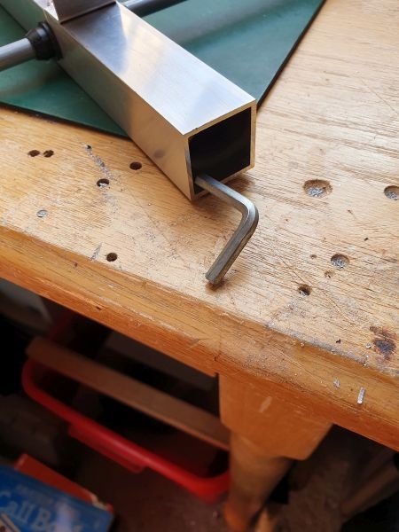
I warmed the bar up with the blow lamp and then created a square which was a lot easer than a perfect round. I cut it to length and offered it up to the mast which is a telescopic fibreglass landing net handle. It's 2m long so the antenna is a full wavelength off the ground. I will use the antenna in horizontal mode so I drilled the holes through the sides of the boom. Tightening it up I could not get it to grip without drooping at the nose. It needed something better to grip the mast. I cut a bit of aluminium sheet, filed it up and drilled it out for the bolt. I then folded the sides to create an open box section. Popped it in the vice an filed a half moon across the open edges in the middle. To create a better grip I put a bit of self adhesive heat shrink on the top section of the mast which did the trick. I can finger tighten it to the mast with the wing nuts and it holds the horizontal now with no nose dive.
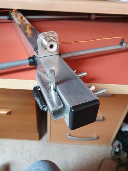
You can see that I received the end caps for the boom. Drilling out for the bolt means that I cant fit the Allen key inside, the end caps are a very tight fit anyway so I have trapped it in the bracket for transport. I shoved a couple of spare wing nuts inside the boom in case I lose one. Screwdriver prizing job to get the end cap off but better than not having a nut when you have carted it to the top of a hill.
I opted to make my own so I got a length of 5mm threaded bar and I found some matching wing nuts to go with it. 1m of bar and 10 wing nuts were less than the price of one U bolt!
I warmed the bar up with the blow lamp and then created a square which was a lot easer than a perfect round. I cut it to length and offered it up to the mast which is a telescopic fibreglass landing net handle. It's 2m long so the antenna is a full wavelength off the ground. I will use the antenna in horizontal mode so I drilled the holes through the sides of the boom. Tightening it up I could not get it to grip without drooping at the nose. It needed something better to grip the mast. I cut a bit of aluminium sheet, filed it up and drilled it out for the bolt. I then folded the sides to create an open box section. Popped it in the vice an filed a half moon across the open edges in the middle. To create a better grip I put a bit of self adhesive heat shrink on the top section of the mast which did the trick. I can finger tighten it to the mast with the wing nuts and it holds the horizontal now with no nose dive.
You can see that I received the end caps for the boom. Drilling out for the bolt means that I cant fit the Allen key inside, the end caps are a very tight fit anyway so I have trapped it in the bracket for transport. I shoved a couple of spare wing nuts inside the boom in case I lose one. Screwdriver prizing job to get the end cap off but better than not having a nut when you have carted it to the top of a hill.
Ian


-
PanBiker
- Site Administrator
- Posts: 16449
- Joined: 23 Jan 2012, 13:07
- Location: Barnoldswick - In the West Riding of Yorkshire, always was, always will be.
Re: Amateur Radio Homebrew (Shack Culture)
Thanks Kev, it meters out very well even indoors so It should be bob on out in the clear. Will find out on this expedition anyway.
Ian
-
PanBiker
- Site Administrator
- Posts: 16449
- Joined: 23 Jan 2012, 13:07
- Location: Barnoldswick - In the West Riding of Yorkshire, always was, always will be.
Re: Amateur Radio Homebrew (Shack Culture)
I set the antenna up today to give it a test. Looking at the propagation predictions for this week there was tropospheric ductingfrom the East coast over to Norway. Fired up the transceiver and I couldn't get any drive out of it on SSB. I checked the antenna and that was fine. Either a fault on the transceiver or it could be interference from the WiFi mast which is powered from the power post behind our pitch.  There are three other masts on the site which are all radio linked by flat plate antennas. The links would be up in the GHz band along with their broadcast frequency so should not interfere as such unless it is a proximity issue. I can test this by running the transceiver off site which I will do at some point.
The WiFi let's me post on one guy of course but may be spoiling my fun.
The WiFi let's me post on one guy of course but may be spoiling my fun.
Ian
-
Stanley
- Global Moderator
- Posts: 90301
- Joined: 23 Jan 2012, 12:01
- Location: Barnoldswick. Nearer to Heaven than Gloria.
Re: Amateur Radio Homebrew (Shack Culture)
I hope it works for you Ian.....
Stanley Challenger Graham
Stanley's View
scg1936 at talktalk.net
"Beware of certitude" (Jimmy Reid)
The floggings will continue until morale improves!
Stanley's View
scg1936 at talktalk.net
"Beware of certitude" (Jimmy Reid)
The floggings will continue until morale improves!
-
PanBiker
- Site Administrator
- Posts: 16449
- Joined: 23 Jan 2012, 13:07
- Location: Barnoldswick - In the West Riding of Yorkshire, always was, always will be.
Re: Amateur Radio Homebrew (Shack Culture)
Mentioned in another thread, I gave my C58 transceiver a quick check away from the site and it was still the same, no drive output shown on the meter when transmitting on SSB, (Single Side Band). SSB is a very efficient mode as you get more bangs for your buck so to speak, very important particularly when using low power. Briefly it works like this. A standard AM (Amplitude Modulated) signal is made up of a carrier drive signal which contains two, (upper and lower) side bands which are identical mirrors either side of the carrier. You need quite a high, (relative) power overhead (bandwidth) to transmit this form of modulation as you have to transmit the carrier and both side bands. On the receiving end you then have to process the carrier and strip out the side bands which contain the signal information. You can cut out a lot of this overhead if you use SSB modulation. Both side bands are the same so you only need one of them so you can cut out the other. Further savings can be made by suppressing the carrier signal as it can be regenerated within a suitable receiver anyway. Much more efficient, SSB is the predominant modulation method used on the amateur bands for telephony communication. Here is the Wiki on SSB Modulation.
Clearly further investigations are required.
I set up a test with another Barlick amateur (Mick (M7MCG)) yesterday who lives just across town. We first tested the output with FM modulation which worked fine and as a full carrier mode showed the output as constant drive on the meter as expected. Audio was reported as Q5 which is as good as it gets. The audio quality is of importance as it indicates that the microphone processing and amplification stages in the transmitter are working correctly. This rules out the front end stages as being the problem as those stages are shared regardless of the final modulation mode used.
Mick had to swap transceivers to give me a test on SSB. We agreed a test contact in the SSB portion of the 2m band on 144.330MHz. I took him a few minutes to set his end up so I waited to see if I could hear him on the agreed frequency. Pleased to say his transmission was received without any problem. When I transmitted though I got no indication on the meter that I was radiating a signal. With SSB modulation you don't have a carrier signal as that is suppressed, you should see and indication on the meter though when you speak into the microphone which reflects the drive to the chosen, (upper USB or lower LSB) side band You only see the audio drive on the peaks of speech but you should see this reflected on the meter. According to the meter there was no drive at all. Pleased to say though that my transmission was reported as perfect. So, nothing wrong with the the actual transmitter. It looks like a metering problem when in SSB mode. This is good news as such, I could live with knowing that it is correctly radiating a signal but not seeing it on the meter. However it's not right so deserves a coat of looking at.
Fortunately Standard Radio equipment was always supplied with comprehensive information for the user. The user manual is 70 pages long but only the first 20 pages are dedicated to the operating instructions. The other 50 pages contain a full technical circuit description, operational block diagram, exploded views and full disassembly instructions, PCB layout diagrams, full parts list of all components with part numbers, description, type and circuit location and full circuit schematic diagram. I shall be poking around the metering circuitry and description to look for likely culprits for the problem. Now I know that it is actually working I can get it on the bench and utilise the dummy load that I built to hopefully aid in trace and repair.
Ian

Re: Amateur Radio Homebrew (Shack Culture)
Good luck with the fault finding. Keep us posted.
Memories fading, but is it still the case for AT's that it's LSB below 10 Mhz, and USB above? So 144 Mhz would be 'in the uppers'.
Also I recall that (counterintuitively) the VHF air comms still use A3E with full carrier. Legacy mainly I guess, but the mode is more forgiving of slight mistuning, not likely to be a factor with modern technology, and the capture effect of F3E is still a factor.
Born to be mild
Sapere Aude
Ego Lego
Preferred pronouns - Thou, Thee, Thy, Thine
My non-working days are Monday - Sunday
Sapere Aude
Ego Lego
Preferred pronouns - Thou, Thee, Thy, Thine
My non-working days are Monday - Sunday
-
PanBiker
- Site Administrator
- Posts: 16449
- Joined: 23 Jan 2012, 13:07
- Location: Barnoldswick - In the West Riding of Yorkshire, always was, always will be.
Re: Amateur Radio Homebrew (Shack Culture)
Your recollections are still good David regarding conventional usage on the AR bands On the aircraft side you are also correct. I have one of my band selections set up on my FT897 to cover the 133MHz band AM which tends to get the traffic for Leeds Bradford and Manchester on approach and departure. Once on the ground I think they use channelised FM for local control from the tower with taxiing information etc.
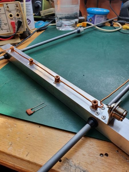
Back to the repair, here is the bit of the schematic of immediate interest. It's the metering circuitry arrangement, or most of it, there is a bit more to the immediate right just past a natural fold in the diagram. It's basically a lamp used as a back light for the LCD display. Controlled by the three position slide switch shown in the diagram.
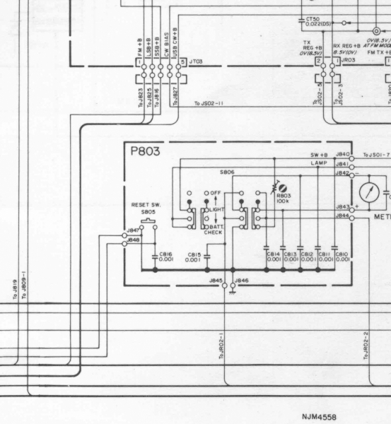
This switch is suspect as it's now 40 years old and will get a coat of looking at and some switch cleaner, this fault could be as easy as that. There is also an associated variable resistor in the circuit. That is also suspect. I will have to check in the circuit description but I doubt it will get down to this granular level, there may be reference in the alignment instructions though as to it's intended usage, probably used for meter sensitivity.
The circuit description has the Japanese delights of the younger amps. Pre-amplifiers to you and I. There is no proper equivalent for the term in the Japanese language. I first came across this anomaly in the first circuit descriptions of JVC Video Recorders when I was mending stuff like that, They compiled the confusion by employing six microprocessor in the design but they referenced them all as IC1 despite being on different boards and used for completely different control tasks in the machine! It's a wonder anything ever got repaired.
Back to the repair, here is the bit of the schematic of immediate interest. It's the metering circuitry arrangement, or most of it, there is a bit more to the immediate right just past a natural fold in the diagram. It's basically a lamp used as a back light for the LCD display. Controlled by the three position slide switch shown in the diagram.
This switch is suspect as it's now 40 years old and will get a coat of looking at and some switch cleaner, this fault could be as easy as that. There is also an associated variable resistor in the circuit. That is also suspect. I will have to check in the circuit description but I doubt it will get down to this granular level, there may be reference in the alignment instructions though as to it's intended usage, probably used for meter sensitivity.
The circuit description has the Japanese delights of the younger amps. Pre-amplifiers to you and I. There is no proper equivalent for the term in the Japanese language.
Ian
-
Stanley
- Global Moderator
- Posts: 90301
- Joined: 23 Jan 2012, 12:01
- Location: Barnoldswick. Nearer to Heaven than Gloria.
Re: Amateur Radio Homebrew (Shack Culture)
A page of pure radioese.... Good luck with the hunt Ian.
Stanley Challenger Graham
Stanley's View
scg1936 at talktalk.net
"Beware of certitude" (Jimmy Reid)
The floggings will continue until morale improves!
Stanley's View
scg1936 at talktalk.net
"Beware of certitude" (Jimmy Reid)
The floggings will continue until morale improves!